
 Medical Molds
 Packaging Molds
 Personal Care Molds
 Electronic Molds
 Automotive Molds
 Home Appliance Molds
 Special Molds
 Design & Engineering
 Production & Manufacturing
 Global Presence
 Business Scope
 Component Solutions
 Product Assembly
 Quality Management
 Medical Device Manufacturing



Automotive full-width light guide strip mold
FEATURES
The Foundation — Manufacturing Infrastructure That Eliminates Client Risk
1.1 Precision Machining Capabilities
The foundation of Ansix‘s light guide strip mold manufacturing rests on a machining infrastructure engineered for optical-grade tolerances. The core machining fleet includes 5-axis high-speed machining centers capable of maintaining tolerances within ±0.002mm across complex, freeform optical geometries . For full-width light guide strips—which often exceed 1.2 meters in length and demand seamless light transmission across the entire span—this level of precision is non-negotiable.
The machining workflow integrates:
High-precision CNC systems for rough and semi-finish machining of core and cavity blocks
Wire EDM and precision EDM (sinker) capabilities for micro-optical patterns and fine gate details
Mirror-polishing stations achieving surface roughness below Ra 0.05μm on optical surfaces
This equipment base does not exist for showroom purposes. Each machine addresses a specific failure mode that plague light guide molds: visible parting lines that scatter light, gate vestiges that create dark spots, and surface imperfections that degrade uniformity.
-
Mold Description
Product Materials:
PC PMMA
Mold Material:
S136ESR
Number of Cavities:
2
Glue Feeding Method:
Hot runner
Cooling Method:
Water cooling
Molding Cycle
42.5s
- The mold manufacturing process and product material selection
Tooling Steel Selection and Heat Treatment
The steel chosen for a light guide strip mold determines its operational life and optical consistency over millions of shots. Ansix specifies hardened tool steels (H13, 2344, or equivalent) for cores and cavities, selected based on the optical resin to be processed and the expected production volume . For glass-filled engineering resins used in structural light guide applications, high-hardness tool steels are mandated to resist abrasion over 300,000+ cycles .
Heat treatment is not outsourced to the lowest bidder. Documented heat treatment curves accompany every mold, ensuring that hardness uniformity is maintained across the entire cavity surface. This directly impacts optical consistency: uneven steel hardness leads to uneven polishing, which leads to uneven light extraction.
-
Injection Molding Machine Fleet
Ansix operates 260 injection molding machines across four production facilities in China and Vietnam, with tonnage ranging from 30 tons to 2,800 tons . For full-width light guide strips, the critical capability is not merely tonnage but shot-to-shot repeatability. The press fleet is equipped with:
Servo-electric drives for precise injection velocity control
Centralized MES connectivity for parameter lockout and traceability
Automated part handling and conveyor systems integrated with downstream inspection
The significance for the client is straightforward: the same machine that molds your T0 samples will mold your production parts. No transfer to a different facility, no re-qualification, no process drift between validation and mass production.
Part Two: The Engineering Process — From Concept to Production Tool
2.1 Design for Manufacturability (DFM): The First Cost-Saving Opportunity
The DFM phase for a full-width light guide strip mold is where the majority of downstream problems are prevented or permanently baked in. Ansix‘s DFM process begins with a comprehensive analysis of the client’s 3D model, focusing on:
Flow balance across full-width geometry. A 1.2-meter light guide strip presents a fundamentally different filling challenge than a 150mm strip. The pressure drop from gate to end-of-fill can vary dramatically across the length, leading to short shots, excessive packing pressure at the gate, and dimensional inconsistency. Ansix‘s DFM identifies these risks before steel is cut.
Gate location and vestige control. The gate location determines weld line positions, flow front progression, and pressure distribution. For full-width strips, Ansix typically recommends valve-gate sequential control to manage pressure decay across the long, thin cavity, preventing visible weld lines from crossing illumination zones . Gate vestige is specified to eliminate secondary trimming operations .
Wall thickness transitions. Full-width light guide strips often feature variable thickness—thicker at mounting points, thinner at light extraction zones. These transitions are thermal management challenges: thick sections cool slower, creating sink marks and internal voids that appear as dark spots when illuminated. DFM analysis predicts these behaviors and recommends geometry modifications that preserve optical function while improving manufacturability.
The value delivered is concrete: prevents costly redesigns; reduces time-to-market by 3–6 weeks .
2.2 Moldflow Simulation: Predicting Optical Outcomes Before Cutting Steel
Every Ansix light guide project applies systematic Moldflow analysis. The simulations cover:
Melt front progression — identifying where flow fronts meet and whether weld lines will intersect visible optical paths
Pressure distribution — ensuring adequate packing at the far end of full-width strips without over-packing the gate region
Air trap locations — preventing burn marks and incomplete fill that appear as dark defects under illumination
Shear-induced birefringence — predicting residual stress patterns that cause optical distortion
The analysis outcomes drive specific design interventions:
Hot runner systems with zero runner waste — eliminating regrind quality concerns for optical-grade resins
Valve-gate sequential control — managing pressure decay across long, thin cavity shapes
Optimized gate placement — positioning weld lines outside the visible light path
Client value: Moldflow simulation conducted at the DFM stage eliminates the trial-and-error cycle that traditional mold makers accept as inevitable. For a full-width light guide, each physical trial iteration costs 3–5 weeks and significant tool modification expense. Simulation reduces the number of physical trials from an industry-typical 3–4 to 1–2.
2.3 Mold Design Priorities for Optical Quality
The design of a light guide strip mold differs fundamentally from a structural component mold. Ansix‘s design priorities reflect optical outcomes:
Parting line design. Visible witness lines on optical surfaces scatter light and create non-uniform illumination. Ansix specifies mirror-polished parting lines to ensure seamless light transmission . For full-width strips, parting line placement is coordinated with the strip’s curvature to avoid interrupting light extraction features.
Ejection system design. Ejector pin marks are controlled to acceptable tolerances and strategically placed in non-optical areas . For full-width light guides, the ejection strategy must account for the part‘s length and flexibility—ejecting a 1.2-meter strip without warping or surface damage requires distributed, synchronized ejection forces.
Cooling system design. This is perhaps the single most important mold design decision for light guide quality. Uneven cooling creates residual stress, which causes birefringence (optical distortion) and dimensional instability. Ansix designs conformal cooling channels following the natural curvature of the part, maintaining temperature differentials across the cavity within ±2°C . For J-shaped, S-shaped, and wraparound full-width light guide geometries, conformal cooling is not an option—it is a requirement.
Venting system. Adequate venting prevents gas entrapment that causes burn marks and incomplete fill . For full-width strips, venting must be distributed along the entire length of the cavity, not just at the end-of-fill.
Part Three: Material Selection — The Balance Between Optical Performance and Cost
3.1 Polycarbonate (PC) for Functional Lighting
PC is the preferred material for headlamp light guides, exterior signature lighting, and safety-critical illumination . Its advantages include:
Impact strength — safety-grade toughness for exterior applications
Heat deflection temperature up to 130–140°C — surviving under-hood thermal loads
UL94 V-0 flame retardancy available down to 1.0mm
The processing challenge with PC is significant: it requires thorough drying before molding, tight melt residence time control to prevent yellowing, and temperature-controlled mold surfaces due to its higher viscosity . For thick-wall PC light guides (>8mm wall thickness), Ansix specifies low-viscosity optical grades such as Covestro Makrolon® LED2245 or comparable grades to achieve 300°C melt processing without thermal degradation .
3.2 PMMA (Acrylic) for Appearance-Focused Lighting
PMMA is preferred for interior ambient light guides, dome lamps, and tell-tale indicators . Its advantages include:
Superior inherent UV stability — no coating required for interior applications
Highest light transmission (~92%) — maximum optical efficiency
Excellent surface hardness — scratch-resistant
The processing challenge with PMMA is brittleness during assembly handling, and visible weld lines are more pronounced than in PC, requiring meticulous gate positioning . For full-width PMMA light guides, gate location and sequential valve-gate control are critical to managing weld line visibility.
3.3 Glass-Filled Engineering Resins for Structural Light Guides
For applications where the light guide also carries structural load, Ansix employs PPS+40%GF, PBT+GF30, and PEI (Ultem®) . These materials demand high-hardness tool steels (H13, 2344) to resist abrasion over 300,000+ cycles, require enlarged gates to accommodate poor flow characteristics, and achieve UL94 V-0 flame classification with minimal additives .
3.4 Material Specification Summary Report
For every material, Ansix provides a Material Specification Summary Report containing recommended melt and mold temperature windows, shrinkage factors and recommended machining offsets, safety data sheets (SDS), and regulatory compliance declarations, proven cycle times from validated tooling .
Part Four: Manufacturing Process Flow — From Steel to Validated Tool
4.1 The Complete Mold Manufacturing Workflow
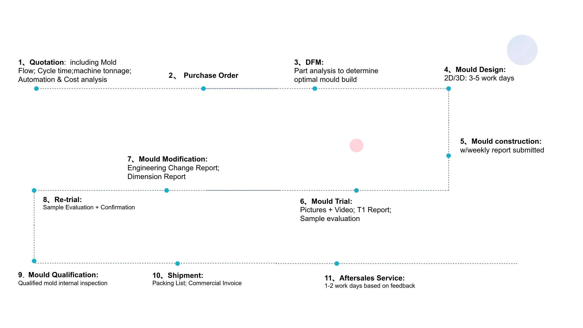
The mold manufacturing process for a full-width light guide strip follows a disciplined sequence:
Design & Engineering — CAD modeling, DFM analysis, mold flow simulation
Material Procurement — Certified steel grades with full traceability
Rough Machining — 5-axis high-speed machining of core and cavity
Heat Treatment — Precise hardening with documented heat treatment curves
Precision Machining — Finish machining, wire EDM for fine features
EDM & Electrode Machining — For complex geometries and micro-optical patterns
Fitting & Assembly — Precision fitting of all mold components
Polishing — Mirror-finish polishing for optical surfaces (Ra < 0.05μm)
Trial Molding — T0 through T3 trials with improvement documentation
Validation — Full dimensional inspection, CPK analysis, wear testing
4.2 Injection Molding Process Discipline as Quality Assurance
The injection molding of full-width light guide strips requires process discipline that goes beyond standard molding practice. Ansix systematizes this discipline through MES-integrated process control:
Parameter standardization. All molding machines are connected to a centralized Manufacturing Execution System (MES). All process parameters—melt temperature profile, hold pressure switchover, injection velocity stages, cooling time, mold temperature zones—are locked after validation and inaccessible to production floor operators . Parameter adjustments require engineering approval and generate a formal change management ticket .
Dimensional stability control. Uneven cooling is the primary enemy of light guide dimensional accuracy. When one section of the part solidifies faster than another, warpage occurs. Ansix addresses this through zone-specific mold temperature management systems that maintain temperature differentials within ±2°C across the molding surface, using separate circuits for core and cavity halves .
SPC monitoring. Full dimensional verification is performed on first and last production pieces of each lot, with SPC charts maintained for all customer-specified critical dimensions .
Part Five: Quality Assurance — From Dimensional Verification to Optical Performance Validation
5.1 In-Process Quality Control
First Article Inspection (FAI) — Comprehensive dimensional verification of first production shots
In-Process Monitoring — Real-time parameter monitoring with automated alarms for deviations
SPC (Statistical Process Control) — Continuous monitoring of critical dimensions
Last Article Inspection — Verification that process stability is maintained through the entire run
5.2 Final Quality Assurance
100% Dimensional Inspection — Critical dimensions verified on every batch
Optical Performance Testing — Light transmission, uniformity, and color consistency verification
Optical scanning for freeform surface conformance where requested
CPK calculation based on 30-piece pre-production run
Environmental Testing — Thermal cycling, humidity, and UV exposure testing as required
5.3 PPAP Documentation
For automotive OEM requirements, Ansix provides full PPAP (Production Part Approval Process) documentation, including:
Design records
Engineering change documents
Process flow diagrams
FMEA (Failure Mode and Effects Analysis)
Control plans
Measurement system analysis
Dimensional results
Material test results
Capability studies (CPK ≥ 1.33)
5.4 Packaging & Logistics
An unprotected optical component arriving with scratches is a reorder. Ansix‘s packaging protocol includes:
Anti-scratch film interlayers between individual components
Tray-based packaging designed for specific part geometry, reversible orientation to prevent surface marking
ESD-safe materials for electronics-adjacent assemblies
Export-qualified palletization documentation for air and ocean freight
Part Six: Competitive Cost Control — Transparent Economics, Not Hidden Surprises
6.1 Material Cost Reduction
Runner-free hot runner configuration eliminates 100% of runner scrap, saving 5–12% material cost directly for every shot produced compared to cold runner alternatives . For high-cost optical-grade PC and PMMA, this material saving compounds significantly over millions of shots.
6.2 Energy Cost Reduction
Servo-electric machines reduce power consumption by 40–70% compared to hydraulic alternatives . For a full-width light guide strip requiring long cycle times due to thick-wall cooling, this energy saving is substantial.
6.3 Design Change Cost Reduction
Modular insert construction means that when product design evolves—gate location changes, wall thickness adjustments—Ansix replaces only the affected insert, not the entire mold. Typical modification cost reduction: 40–60% on design changes .
6.4 Lifecycle Cost Predictability
Every Ansix mold ships with recommended process parameters, spare parts kit, mold maintenance guide with lubrication schedule, and CAD model for reference . Lifetime mold repair at cost—you pay only for material and labor; Ansix adds no markup . This transforms mold maintenance from a variable, unpredictable cost center into a manageable operating expense.
Part Seven: Turnkey Assembly Solutions — Beyond Molded Parts
Ansix does not stop at injection molding. For full-width light guide systems that require integration with LED modules and mounting structures, Ansix offers complete assembly integration, reducing supply chain complexity and vendor management overhead .
Assembly Capabilities
LED module insertion — Precision press-fitting fixtures for PCB-mounted LEDs into light guide mounting bosses
Ultrasonic welding — Joining light guide strip to mounting bracket or housing
Hot staking / Heat staking — Forming plastic bosses to retain PCBs or lenses without separate fasteners
Solvent bonding — Bonding multiple light guide segments into continuous strips (e.g., tail lamp light bars)
Pressure-sensitive adhesive (PSA) application — Backside adhesive application for direct-to-body interior ambient lighting strips
Optical inspection — Vision systems with light output measurement validating LED alignment and light distribution uniformity before shipping
The Single-Source Value Proposition
The challenges of managing separate suppliers—mold maker, molder, assembler—are well documented: finger-pointing when quality issues arise, multiple quality systems, multiple purchase orders, multiple invoices, and shipping parts back and forth for rework .
Ansix‘s single-source solution eliminates these inefficiencies: one responsible party from start to finish. No finger-pointing—just solutions . LED insertion is integrated into the same facility where molding occurs. Defective parts stay at Ansix; rework happens where molding occurred, not shipped across the country .
Your team focuses on vehicle assembly, not chasing components from five different suppliers .
Part Eight: Delivery Efficiency and Service Commitment
8.1 Lead Time Commitments
Mold Complexity Standard Lead Time Expedited Delivery (Premium Fee) Tool Quality Verification
Simple 2-plate mold 10 days N/A Basic dimensional verification
Mid-complexity (standard light guide strip) 25–35 days 20 days with parallel processing Standard validation—T0 samples, DFM report
High-difficulty (multi-cavity, hot runner, thick-wall, large format) 45 days 30–35 days (subject to pre-approval) Enhanced validation—full FAIR inspection before shipment
In all expedited cases, thermo-mechanical simulation cycles and cooling system verification are conducted concurrently with mold machining and are never omitted .
8.2 After-Sales Support
200,000-shot maintenance inspection and cleaning
24-hour emergency response for critical service needs
Perpetual spare parts availability — even for molds built 10 years ago
Lifetime mold repair at cost — no markup on material or labor
8.3 Delivery & Logistics
Custom-designed packaging prevents surface damage and contamination. Anti-static packaging is available for electronic-sensitive components. Traceable labeling with batch and date coding ensures full traceability. Export-worthy crating is provided for international shipments .
Part Nine: Industry Experience — 28 Years of Proven Reliability
Ansix Tech has been designing and manufacturing optical molds and injection-molded components for the automotive industry since 1998—spanning the evolution from halogen to LED to micro-LED lighting architectures .
Documented Performance Metrics
Metric Ansix Performance
Years in continuous operation 28+
Automotive light guide molds delivered 2,000+
Molds currently in active production across customer plants 600+
Total molded light guide parts shipped >500 million
Average mold life achieved (PC/PMMA applications) 1.2 million shots
Maximum mold life recorded (single tool) 3.5 million shots and counting
Customer on-time delivery rate (past 36 months) 99.2%
PPM defect rate (global average across all programs) <800 PPM
Source:
What Customers Say
“Ansix has supplied light guide molds for four consecutive vehicle platforms. Their DFM process consistently identifies manufacturability issues we missed in design. The tools arrive on time and run for years without major intervention.” — Senior Purchasing Manager, European Tier 1 Lighting Supplier
“We migrated light guide production to Ansix from a competitor after persistent quality issues. Within six months of the transition, our assembly line reject rate for light guide-related defects dropped by 70%.” — Production Manager, North American Automotive OEM
“The Ansix team supported us through an unplanned production ramp when our primary supplier failed. They delivered additional tools in half the quoted lead time and maintained 100% quality throughout the surge.” — Supply Chain Director, Asian Automotive Module Manufacturer
Part Ten: The Ansix Promise — Turning Engineering into Client Value
At Ansix, a mold is not a block of steel. It is a revenue-generating asset—a tool designed to produce profit for your business, day after day, million after million .
Every Ansix light guide strip mold is engineered with attention to:
Robustness — steel selection, cooling geometry, and valve-gate systems optimized for million-shot reliability
Efficiency — shortest possible cycle times at consistent quality, maximizing your ROI per machine hour
Serviceability — accessible components, documented maintenance procedures, and spare parts availability that eliminates production interruptions
The company‘s credibility in automotive light guide molding is built on completed programs, not hypothetical capabilities. Whether the requirement is a Mercedes-Benz front transparent light guide light bar, an Audi headlamp light guide, or a full-width signature lighting strip for a next-generation EV platform, the Ansix approach remains consistent: understand the optical outcome required, engineer the mold to deliver it, and control the process to repeat it millions of times .
Ansix Tech — Precision Engineering Meets Uncompromising Value.
Ansix Tech Co Ltd
If you have any plans related to Automotive full-width light guide strip mold , you can contact us at any time. We will turn your ideas into reality, let you realize your dreams, and obtain large orders from the market. Our contact information is info@ansixtech.com. Or contact our CTO, mail: stephen@ansixtech.com
#www.ansixtech.com #ansixtech.com #Automotive full-width light guide strip mold #Automotive full-width light guide strip mold Tooling #Automotive full-width light guide strip mold injection mold companies #Ansix #Ansix moulds #Ansix china #Ansix tech china #Ansix tech company #Ansix facotry #Ansix Tooling #Ansix tool #Automotive full-width light guide strip mold injection molding #Automotive full-width light guide strip mold injection tools #Automotive full-width light guide strip mold injection moulds #Ansix moulding company #Ansix molding #ansix tooling #Automotive full-width light guide strip mold plastic mould #Automotive full-width light guide strip mold plastic tools #Ansix Tech #Ansix molds #Ansix injection molding #Ansix mold factory #Automotive full-width light guide strip mold injection molding Customized #Ansix mold factory #Automotive full-width light guide strip mold china #Automotive full-width light guide strip mold molds #injection factory for Automotive full-width light guide strip mold #Automotive full-width light guide strip mold injection molding #Automotive full-width light guide strip mold injection molding factory #injection molding company #Automotive full-width light guide strip mold injection mold companies #Automotive full-width light guide strip mold Tooling #Automotive full-width light guide strip mold mold limited #Ansix mold china #Ansix companies for Automotive full-width light guide strip mold #Ansix company China #Automotive full-width light guide strip mold facotry #Ansix Tech #Ansix Tech mould #Automotive full-width light guide strip mold injection moulding #Automotive full-width light guide strip mold injection moulding company #Ansix Automotive full-width light guide strip mold parts injection mold companies #Automotive full-width light guide strip mold injection molding companies china #Automotive full-width light guide strip mold china factory #Ansix moulding companies #Ansix molding company #Automotive full-width light guide strip mold injection moulding facotry #Ansix Tech mold #Automotive full-width light guide strip mold mould #Automotive full-width light guide strip mold plastic injection molding #ansix plastic mold #Automotive full-width light guide strip mold Mold manufacturing #Automotive full-width light guide strip mold parts manufacturing #Automotive full-width light guide strip mold plastic parts factory #Automotive full-width light guide strip mold injection parts mold #Automotive full-width light guide strip mold PRECISION MANUFACTURING #Automotive full-width light guide strip mold TOOL #China Automotive full-width light guide strip mold mold #Automotive full-width light guide strip mold injection moulding china #Automotive full-width light guide strip mold mould china #china precision mold #Automotive full-width light guide strip mold mold in china #Automotive full-width light guide strip mold mold china #Automotive full-width light guide strip mold Precision molds #High-precision molds #Automotive full-width light guide strip mold High-precision tool #Injection molds #Automotive full-width light guide strip moldFactory #Automotive full-width light guide strip moldCompany #Super Large Injection Mold Factory #Large Tonnage Injection Molding Factory #Automotive full-width light guide strip mold Company #Automotive full-width light guide strip mold Factory #2800T Injection Molding Factory #3000 Ton Injection Molding #4500 Ton Injection Molding Factory #Automotive full-width light guide strip mold Large Mold Injection Molding #Large Plastic Mold Injection Molding Factory #Automotive full-width light guide strip mold Large Injection Mold Manufacturer #Automotive full-width light guide strip mold Plastic Mold Factory #Injection Mold #Plastic Mold