
 Medical Molds
 Packaging Molds
 Personal Care Molds
 Electronic Molds
 Automotive Molds
 Home Appliance Molds
 Special Molds
 Design & Engineering
 Production & Manufacturing
 Global Presence
 Business Scope
 Component Solutions
 Product Assembly
 Quality Management
 Medical Device Manufacturing



Manufacturer of MT Ferrule Fiber Optic Connector Solutions
FEATURES
Understanding MT Ferrule: Technical Foundation and Manufacturing Challenges
An MT ferrule is a rectangular, precision-molded optical connector component that enables the simultaneous alignment and connection of multiple optical fibers, typically 12, 16, 24, or more fibers in a single interface. Unlike single-fiber ceramic ferrules, MT ferrules are generally produced from thermoplastic or thermoset resin compositions, often reinforced with glass or carbon fillers to achieve the dimensional stability and mechanical strength required for repeated mating cycles.
The manufacturing challenge for MT ferrules is formidable. The component requires:
Micro-hole precision: Fiber insertion holes with diameters sized to accommodate 125 μm optical fibers, with position tolerances often measured in single-digit microns. The guide pin bore diameter itself is subject to international standards such as IEC 61300-3-46, which specifies measurement procedures for both guide pin bores and fiber bores in rectangular ferrules.
Pin-bending suppression: During injection molding, the extremely slender core pins that form the fiber holes and guide pin holes are subjected to high-pressure melt flow. Any bending or deflection of these pins results in misaligned bores, directly causing elevated insertion loss. A bending angle of 0.2 degrees or less at the connection end face is often required to achieve ultra-low-loss grade performance.
Material homogeneity: The resin composition must be free of coarse particles or agglomerates that could disrupt the precision of the molded geometry. Filler particle size control, typically requiring maximum particle sizes of 50 μm or less, is a critical material engineering consideration.
End-face geometry: After molding, the ferrule end face undergoes polishing. The hardness differential between the ferrule material and the optical fibers affects the final end-face contour. In one study, a ceramic plate with a Vickers hardness of 2.3 GPa resulted in the harder quartz fibers (9 GPa) protruding relative to the ferrule surface after polishing.
These technical constraints define the manufacturing problem space. Ansix Tech’s value proposition begins with an intimate understanding of these challenges and extends through a systematic engineering approach that converts them into controllable, repeatable production processes.
-
Mold Description
Product Materials:
pps mpo
Mold Material:
S136ESR
Number of Cavities:
2
Glue Feeding Method:
Hot runner
Cooling Method:
Water cooling
Molding Cycle
42.5s
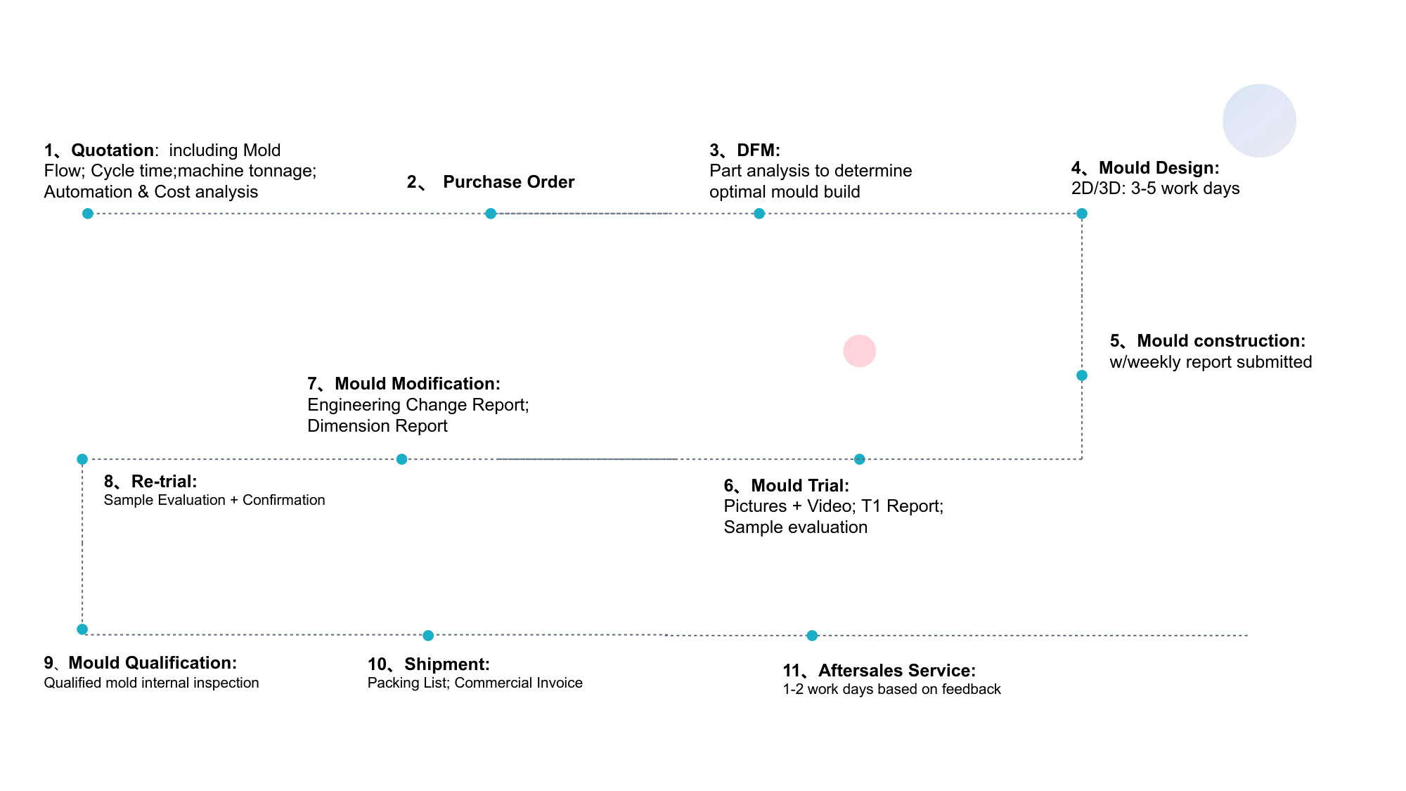
- The mold manufacturing process and product material selection
Core Manufacturing Capabilities: Mold Making for MT Ferrule Components
2.1 DFM and Mold Design Engineering
The foundation of successful MT ferrule manufacturing is the mold. Ansix Tech approaches mold design with a DFM-first philosophy, evaluating the part geometry, material selection, and molding strategy before steel is cut. For MT ferrule applications, the DFM process addresses several critical factors.
Core pin design and support: The slender pins that form the fiber holes and guide pin holes require robust support structures within the mold to resist deflection during injection. Ansix’s mold design engineers develop pin-holding systems that minimize unsupported span lengths and incorporate high-rigidity materials such as tungsten steel for the pins themselves. In high-precision ferrule tooling, tungsten steel pins with diameters as small as 0.1 mm are used, leveraging the material’s high elastic modulus and hardness to maintain straightness under repeated high-pressure injection cycles.
Gating strategy: The location and type of gate directly influence the flow pattern of the molten resin within the cavity. For MT ferrules, a balanced flow front is essential to avoid asymmetric pressure distribution on the core pins. Ansix uses Moldflow simulation to evaluate multiple gate locations and optimize the fill pattern before committing to the mold design.
Cooling optimization: Uniform cooling is critical for dimensional stability. Non-uniform cooling introduces warpage and residual stresses that can cause the ferrule to deviate from flatness or shift the position of the fiber holes. Ansix designs conformal or baffled cooling circuits that follow the ferrule’s geometry and ensure consistent heat extraction across the part.
Parting line and flash control: Flash on the ferrule’s end face or side walls can interfere with mating and polishing. Ansix maintains parting line fit tolerances as tight as 0.005 mm and employs self-locking clamp force compensation to limit flash to ≤0.03 mm on all geometries.
-
Mold Manufacturing Precision and Quality
Ansix’s mold manufacturing infrastructure includes five-axis machining centers, high-speed CNC milling, EDM (electrical discharge machining), and CMM (coordinate measuring machine) inspection. The company reports machining accuracy within ±0.002 mm, automated machining ratios of 70%, and an average of only two mold trials required to achieve qualification.
For MT ferrule tooling, the precision of the core and cavity inserts directly determines the positional accuracy of the fiber holes. Ansix applies:
In-process CMM verification of critical dimensions at each machining stage.
Pin-position inspection using optical measurement systems to verify the x-y coordinates of every core pin relative to the mold datum.
Mold trial with scientific molding methodology to establish the processing window and validate the first-shot part quality.
A key differentiator is Ansix’s ability to fabricate the internal forming components—the pin-holding blocks and core pins—as integrated assemblies. By using oil-cutting (EDM) to form the pin-holding passages directly into the sealing block rather than assembling separate components, Ansix eliminates assembly gaps and cumulative tolerances that could contribute to pin deflection or positional drift.
2.3 Mold Life and Durability
Mold life is a direct contributor to customer cost per part. Ansix engineers MT ferrule molds for extended production runs, targeting tool life of 500,000 to 1,000,000 cycles or more for production tooling. This is achieved through:
Steel selection: High-hardness tool steels (e.g., hardened H13, S136, or equivalent) for cavity and core inserts, with appropriate heat treatment and surface treatments.
Wear-resistant pin materials: Tungsten carbide or tungsten steel for the fiber-hole forming pins.
Cooling circuit design: Properly sized and positioned cooling channels to prevent hot spots that accelerate wear.
Maintenance access: Mold designs that allow quick replacement of wear components without complete disassembly.
Ansix offers a structural warranty on molds and conducts aging tests (e.g., 2,000-cycle wear tests) before shipment, providing documented wear ratios to customers.
3. Injection Molding: Material Selection, Process Optimization, and Quality Control
3.1 Material Selection for MT Ferrule Applications
The resin composition for MT ferrules is a critical determinant of final performance. The material must balance:
Flowability: Sufficient spiral flow length to fill thin, complex geometries without short shots. The resin composition’s spiral flow length (SFL) is a key metric; for MT ferrule applications, SFL values in the range of 60–300 mm are desirable depending on part geometry and molding conditions.
Dimensional stability: Low coefficient of thermal expansion (CTE) and low shrinkage to maintain hole position accuracy across temperature variations. This is particularly important for solder reflow compatibility, where the ferrule may be exposed to 260°C for extended periods.
Mechanical strength: Resistance to pin stubbing and repeated mating cycles. The guide pin holes must withstand repeated insertion of alignment pins without deformation.
Filler homogeneity: The filler (typically silica, carbon, or glass fibers) must be well-dispersed, with no coarse particles or agglomerates exceeding 50 μm, to avoid localized stress concentrations or surface defects.
Common material systems for MT ferrules include:
PPS (Polyphenylene Sulfide): Preferred for its excellent dimensional stability, high-temperature resistance, and precision moldability. PPS with glass fiber reinforcement is a standard choice for MT ferrule bodies.
LCP (Liquid Crystal Polymer): Offers excellent flow for thin-wall sections and very low warpage, suitable for high-density ferrule designs.
PEEK: For applications requiring extreme temperature or chemical resistance, though at higher material cost.
Epoxy-based thermosets: Used in some ferrule designs, particularly where the ferrule body is machined or where specific optical properties are required.
Ansix’s material engineering team works with customers to select the optimal resin grade based on the specific performance requirements, molding constraints, and cost targets of each MT ferrule project. The company has experience processing a wide range of engineering polymers and maintains relationships with major material suppliers to access application-specific grades.
3.2 Injection Molding Process Optimization
Once the mold is qualified and the material selected, the injection molding process must be precisely controlled. The primary objective is to fill the cavity and pack the part without inducing any deflection in the core pins or introducing residual stresses that could cause dimensional drift.
Injection speed profiling: The fill rate must be controlled to minimize pressure spikes on the core pins while still achieving complete fill before the material freezes. Ansix uses multi-stage injection profiles that start slowly to establish a stable flow front, then accelerate through the fill, and finally decelerate as the cavity approaches full.
Packing pressure and time: Over-packing can deflect core pins; under-packing results in shrinkage voids and dimensional instability. The packing profile is optimized using cavity pressure sensors or short-shot studies to establish the minimum pressure required for dimensional conformance.
Melt and mold temperature control: For PPS and similar high-temperature engineering resins, melt temperatures of 290–380°C and mold temperatures of 120–160°C are typical. Precise temperature control is essential for consistent viscosity and crystallization behavior.
Cycle time optimization: While cycle time is a cost driver, aggressive cycle reduction can compromise part quality. Ansix balances productivity with quality by optimizing cooling time based on actual part temperature at ejection, not a fixed timer.
Ansix’s molding facilities are equipped with modern injection molding machines from Fanuc, Sumitomo, Toshiba, Nissei, Engel, and Arburg, among others, with tonnages from 30 to 2,800 tons. For MT ferrule applications, the smaller-tonnage machines with high-precision shot control are typically employed.
3.3 In-Mold Process Monitoring and Closed-Loop Control
For high-precision components such as MT ferrules, post-process inspection alone is insufficient to guarantee quality. Ansix implements in-process monitoring to detect deviations before they produce scrap.
Cavity pressure sensing: Pressure sensors positioned at the end of fill or in the packing phase provide real-time feedback on the filling and packing conditions. Deviations from the established process window trigger alarms or automatic process adjustments.
Temperature monitoring: Thermocouples or infrared sensors monitor mold surface temperature at critical locations. Drift in mold temperature can affect shrinkage and dimensional stability.
Machine process data logging: Injection speed, pressure, screw position, and cycle time are recorded for every shot. This data enables statistical process control (SPC) and traceability.
The integration of sensor data with the MES (Manufacturing Execution System) allows closed-loop control of part weight and critical dimensions, maintaining week-to-week dimensional stability within ±0.02 mm for precision ferrule components.
4. Product Validation and NPI Process Planning
4.1 Design Verification and Moldflow Analysis
Before mold manufacturing begins, Ansix performs Moldflow simulation to predict filling behavior, pressure distribution, temperature gradients, and potential defects. For MT ferrule molding, the simulation specifically evaluates:
Core pin deflection: By modeling the melt pressure distribution along the pins, the simulation identifies regions of high unbalanced force that could bend the pins.
Weld line location: Weld lines in the ferrule body can reduce mechanical strength and create cosmetic defects. The simulation predicts weld line positions so the gate and flow strategy can be adjusted.
Air trap prediction: Trapped air can cause burn marks or incomplete fill. Simulation identifies potential air traps and informs venting design.
After mold trial, Ansix performs first-article inspection (FAI) covering all critical dimensions, including fiber hole positions, guide pin bore diameter and position, end-face flatness, and overall part dimensions. For MT ferrules, end-face geometry may be measured using a dedicated MT ferrule end-face interferometer, which characterizes the radius of curvature and fiber protrusion/retraction.
4.2 NPI Process Planning and Pilot Production
Ansix’s NPI process for MT ferrule projects follows a structured gateway approach:
T0 — Mold trial and process window establishment: The first mold trial establishes a baseline process. Short-shot studies, pressure-drop studies, and gate freeze studies are conducted to define the processing window.
T1 — First-article validation: Parts from the T1 trial undergo full dimensional inspection and, if required, functional testing (insertion loss, return loss) in collaboration with the customer or a third-party optical test lab.
T2 — Process capability validation: A pilot run of 100–500 pieces is produced to statistically validate process capability. Cp/Cpk values are calculated for critical dimensions, with targets typically ≥1.33 and ≥1.67 for safety-critical or high-precision features.
T3 — Production readiness: The mold and process are locked. Documentation including process sheets, inspection standards, and control plans is finalized. Pre-production samples are submitted for customer approval.
This staged approach reduces the risk of launching a process that cannot sustain quality at volume. Ansix’s average of only two mold trials to reach qualification reflects the effectiveness of this methodology.
5. High-Volume Production, Quality Assurance, and Delivery
5.1 Scaling from Pilot to Mass Production
For MT ferrule components destined for data center, telecommunications, or high-performance computing applications, production volumes can reach millions of parts annually. Ansix’s manufacturing infrastructure supports this scale through:
Multi-cavity mold design: Where part geometry and molding economics permit, Ansix designs molds with 4, 8, or more cavities to multiply output per cycle. For MT ferrules, multi-cavity tooling requires exceptional balance in the feed system and cooling to ensure all cavities produce identical parts.
Automated part handling: Robots and automated conveyance systems remove parts from the mold and transfer them to downstream operations, reducing labor cost and human variability.
Lights-out manufacturing: For stable, high-volume processes, Ansix can operate molding cells with minimal operator intervention, using automated monitoring and alarm systems.
5.2 Quality Assurance System
Ansix maintains a comprehensive quality management system certified to ISO 9001, IATF 16949, ISO 13485, and ISO 14001. For MT ferrule manufacturing, the quality assurance framework includes:
Incoming material control: Every resin lot is verified against specifications for melt flow rate, filler content, and particle size distribution. Certificates of analysis from the material supplier are reviewed, and periodic independent testing confirms compliance.
In-process inspection: Critical dimensions are measured at defined intervals during production. Statistical process control charts track dimensional trends, and out-of-control conditions trigger containment and corrective action.
Final inspection and testing: Depending on customer requirements, final inspection may include dimensional verification, visual inspection for flash and surface defects, and functional testing. For MT ferrules, critical functional characteristics include:
Fiber hole diameter and position (measured optically or with pin gauges).
Guide pin bore diameter and roundness (per IEC 61300-3-46 methodology).
End-face geometry (radius of curvature, apex offset, fiber height).
Insertion loss and return loss when assembled with fiber ribbon and mated to a reference connector.
Traceability: Every production lot is traceable to the raw material batch, molding machine, mold, and process parameters. This enables rapid root-cause analysis in the event of a quality excursion and supports customer requirements for lot-level documentation.
5.3 Delivery and After-Sales Support
Ansix’s four production bases in China and Vietnam provide geographic flexibility and supply chain resilience. For MT ferrule customers, this means:
Regional supply options: Depending on the customer’s manufacturing footprint, production can be allocated to the most advantageous base for tariff, logistics, and lead-time considerations.
Inventory management: Ansix can support VMI (Vendor Managed Inventory) or consignment stock arrangements for high-volume programs.
After-sales engineering support: For mold maintenance and repair, Ansix maintains in-house EDM and machining capabilities. Most repairs (spot welding, insert replacement) are completed within 24 hours without shipping to external vendors.
6. Cost Engineering: The Ansix Advantage
6.1 Material and Design Optimization
The most significant cost reductions in MT ferrule manufacturing are achieved at the design stage. Ansix’s cost engineering approach includes:
Wall thickness optimization: Reducing wall thickness where mechanically permissible reduces material consumption and cycle time. For glass-filled engineering resins, Ansix typically achieves 15–25% material savings compared to conventionally designed parts by optimizing wall thickness and eliminating unnecessary material accumulation.
Gate and runner optimization: Hot runner systems eliminate runner waste, which is particularly valuable for expensive engineering resins. For cold runner designs, Ansix optimizes runner diameter and layout to minimize scrap.
Yield improvement: Process optimization and in-process monitoring reduce scrap rates. The cost of scrap in MT ferrule production is high because each part contains significant material and processing value. Even a 1% yield improvement can translate to meaningful cost savings at volume.
6.2 Process Efficiency
Ansix’s molding processes are designed for efficiency:
Cycle time reduction: Optimized cooling and packing profiles, combined with high-performance injection units, reduce cycle time by 20–35% compared to industry averages.
Energy efficiency: Modern all-electric injection molding machines, such as those from Fanuc and Sumitomo, reduce energy consumption per part.
Automation: Automated part removal, inspection, and packaging reduce labor content.
6.3 Total Cost of Ownership
Ansix positions its value proposition in terms of total cost of ownership rather than unit price alone. A mold that lasts longer, a process that produces fewer defects, and a supply chain that delivers reliably all contribute to lower overall cost. The company’s approach is to document these factors transparently so that customers can make informed decisions.
7. Conclusion: Translating Technical Excellence into Customer Value
For manufacturers of MT Ferrule fiber optic connectors, the choice of a molding and mold-making partner is a strategic decision that affects product performance, production economics, and supply chain reliability. Ansix Tech’s proposition is built on the systematic translation of technical capabilities into customer value:
Technical Capability Customer Value
±0.002 mm mold machining accuracy Consistent fiber hole position, low insertion loss
Moldflow simulation for pin deflection Fewer mold trials, faster time-to-market
Tungsten steel core pins with robust support Stable production, extended mold life
In-mold pressure and temperature monitoring Week-to-week dimensional stability ±0.02 mm
IATF 16949 and ISO 13485 certified quality system Documented quality, audit-ready supply chain
Four production bases in China and Vietnam Supply chain resilience, geographic flexibility
Staged NPI process (T0–T3) Reduced launch risk, validated process capability
The MT ferrule is a component where microns matter. A positional deviation of a few micrometers in a fiber hole translates directly into increased insertion loss; a fraction of a degree of pin bending can push a connector out of the ultra-low-loss grade specification. Ansix Tech’s manufacturing philosophy recognizes that these technical requirements cannot be met by inspection alone—they must be designed into the mold, built into the process, and verified at every stage. By doing so, Ansix converts the language of microns, tolerances, and material rheology into the outcomes that customers ultimately value: reliable optical performance, competitive cost, and dependable delivery.
Ansix Tech Co Ltd
If you have any plans related to Manufacturer of MT Ferrule Fiber Optic Connector Solutions , you can contact us at any time. We will turn your ideas into reality, let you realize your dreams, and obtain large orders from the market. Our contact information is info@ansixtech.com. Or contact our CTO, mail: stephen@ansixtech.com
#www.ansixtech.com #ansixtech.com #Manufacturer of MT Ferrule Fiber Optic Connector Solutions #Manufacturer of MT Ferrule Fiber Optic Connector Solutions tooling #Manufacturer of MT Ferrule Fiber Optic Connector Solutions injection mold companies #Ansix #Ansix moulds #Ansix china #Ansix tech china #Ansix tech company #Ansix facotry #Ansix Tooling #Ansix tool #Manufacturer of MT Ferrule Fiber Optic Connector Solutions injection molding #Manufacturer of MT Ferrule Fiber Optic Connector Solutions injection tools #Manufacturer of MT Ferrule Fiber Optic Connector Solutions injection moulds #Ansix moulding company #Ansix molding #ansix tooling #Manufacturer of MT Ferrule Fiber Optic Connector Solutions plastic mould #Manufacturer of MT Ferrule Fiber Optic Connector Solutions plastic tools #Ansix Tech #Ansix molds #Ansix injection molding #Ansix mold factory #Manufacturer of MT Ferrule Fiber Optic Connector Solutions injection molding Customized #Ansix mold factory #Manufacturer of MT Ferrule Fiber Optic Connector Solutions china #Manufacturer of MT Ferrule Fiber Optic Connector Solutions molds #injection factory for Manufacturer of MT Ferrule Fiber Optic Connector Solutions injection molding #Manufacturer of MT Ferrule Fiber Optic Connector Solutions injection molding factory #injection molding company #Manufacturer of MT Ferrule Fiber Optic Connector Solutions injection mold companies #Mold for Manufacturer of MT Ferrule Fiber Optic Connector Solutions #Manufacturer of MT Ferrule Fiber Optic Connector Solutions limited #Ansix mold china #Ansix companies for Manufacturer of MT Ferrule Fiber Optic Connector Solutions #Ansix company China #Manufacturer of MT Ferrule Fiber Optic Connector Solutions facotry #Ansix Tech #Ansix Tech mould #Manufacturer of MT Ferrule Fiber Optic Connector Solutions injection moulding #Manufacturer of MT Ferrule Fiber Optic Connector Solutions injection moulding company #Ansix Manufacturer of MT Ferrule Fiber Optic Connector Solutions parts injection mold companies #Manufacturer of MT Ferrule Fiber Optic Connector Solutions injection molding companies china #Manufacturer of MT Ferrule Fiber Optic Connector Solutions china factory #Ansix moulding companies #Ansix molding company #Manufacturer of MT Ferrule Fiber Optic Connector Solutions injection moulding facotry #Ansix Tech mold #Manufacturer of MT Ferrule Fiber Optic Connector Solutions mould #Manufacturer of MT Ferrule Fiber Optic Connector Solutions plastic injection molding #ansix plastic mold #Manufacturer of MT Ferrule Fiber Optic Connector Solutions Mold manufacturing #Manufacturer of MT Ferrule Fiber Optic Connector Solutions parts manufacturing #Manufacturer of MT Ferrule Fiber Optic Connector Solutions plastic parts factory #Manufacturer of MT Ferrule Fiber Optic Connector Solutions injection parts mold #Manufacturer of MT Ferrule Fiber Optic Connector Solutions PRECISION MANUFACTURING #Manufacturer of MT Ferrule Fiber Optic Connector Solutions TOOL #China Manufacturer of MT Ferrule Fiber Optic Connector Solutions mold #Manufacturer of MT Ferrule Fiber Optic Connector Solutions injection moulding china #Manufacturer of MT Ferrule Fiber Optic Connector Solutions mould china #china precision mold #Manufacturer of MT Ferrule Fiber Optic Connector Solutions mold in china #Manufacturer of MT Ferrule Fiber Optic Connector Solutions mold china #Manufacturer of MT Ferrule Fiber Optic Connector Solutions Precision molds #High-precision molds #Manufacturer of MT Ferrule Fiber Optic Connector Solutions High-precision tool #Injection molds #Manufacturer of MT Ferrule Fiber Optic Connector SolutionsFactory #Manufacturer of MT Ferrule Fiber Optic Connector SolutionsCompany #Super Large Injection Mold Factory #Large Tonnage Injection Molding Factory #Manufacturer of MT Ferrule Fiber Optic Connector Solutions Company #Manufacturer of MT Ferrule Fiber Optic Connector Solutions Factory #2800T Injection Molding Factory #3000 Ton Injection Molding #4500 Ton Injection Molding Factory #Manufacturer of MT Ferrule Fiber Optic Connector Solutions Large Mold Injection Molding #Large Plastic Mold Injection Molding Factory #Manufacturer of MT Ferrule Fiber Optic Connector Solutions Large Injection Mold Manufacturer #Manufacturer of MT Ferrule Fiber Optic Connector Solutions Plastic Mold Factory #Injection Mold #Plastic Mold