


Headboard Gas-Assisted Molding
FEATURES
This comprehensive manufacturing solution framework is structured into five key pillars: (1) technological infrastructure that builds client trust; (2) core mold manufacturing competencies quantified with specific metrics; (3) injection molding process control that eliminates quality anxiety; (4) full-service lifecycle support reducing client management costs; and (5) differentiated value propositions that address common industry pain points with actionable guarantees.
-
Mold Description
Product Materials:
PA+GF30 PP+GF25
Mold Material:
S136ESR
Number of Cavities:
1
Glue Feeding Method:
COLD runner
Cooling Method:
Water cooling
Molding Cycle
42.5s
- The mold manufacturing process and product material selection
Technological Foundation: Building Client Trust with Hard Infrastructure
1.1 Mold Manufacturing Equipment – Precision at Every Level
Ansix Tech operates a state-of-the-art mold manufacturing facility equipped with five-axis high-speed CNC machining centers capable of achieving 0.002mm precision on complex contoured surfaces. This capability directly translates to client value through seamless parting lines free of burrs requiring secondary finishing—eliminating manual deburring operations and reducing post-processing costs by up to 15%. Slow wire EDM systems enable the machining of micro-pores and narrow slots down to 0.03mm, facilitating intricate gas channel geometries with precision that prevents thin-wall deformation.
Our complete equipment portfolio includes EDM spark erosion systems, wire-cut EDM, precision surface grinders, and deep-hole drilling machines. Every tool path is verified through digital simulation before cutting begins, ensuring right-first-time machining and eliminating costly rework.
-
Injection Molding Machine Fleet – Performance at Scale
Ansix Tech maintains an extensive injection molding machine fleet spanning 30 tons to 4,000 tons clamping force, accommodating headboard components from compact designs to oversized king-size panels. All machines are all-electric servo-driven, delivering exceptional repeatability at ±0.1% across all critical parameters. This precision ensures that every production shot maintains identical quality to the first—eliminating batch-to-batch variation concerns and reducing quality inspection burden [7†L43-L47].
The fleet is fully integrated with machine networking and automated data acquisition systems, enabling real-time monitoring of key process parameters. Centralized material drying systems ensure consistent moisture content across all production lines. Automated material handling from silos to molding machines eliminates contamination risks and manual material changeover delays.
1.3 Inspection and Metrology – Data-Driven Quality Assurance
Every mold and production part undergoes rigorous dimensional verification using CMM (Coordinate Measuring Machine) with 0.001mm resolution and high-precision optical measurement systems. Each mold is shipped with a full dimensional compliance report, with critical-to-quality features achieving Cpk ≥ 1.33—a statistical guarantee that 99.993% of production falls within specification limits. This proactive quality verification eliminates downstream assembly fit issues and customer rejections.
II. Core Mold Manufacturing Competencies: Quantifiable Value Delivery
2.1 Mold Life Expectancy – Maximizing ROI Through Strategic Material Selection
The fundamental client question centers on mold longevity: how many cycles before costly rework or replacement becomes necessary? Ansix Tech delivers a definitive answer through precision material selection.
Mold Steel Selection Framework
Component Material Grade Key Properties Application Scenario
Mold Base P20 (1.2311) Pre-hardened, good machinability Cost-effective structural foundation
Cavity/Core for Standard Plastics NAK80 / S136H (HRC 36-40) High polishability, good wear resistance ≤500,000 cycles
Cavity/Core for Glass-Filled Materials S136 / H13 / SKD61 (HRC 48-52) Superior wear resistance, thermal stability ≥500,000 cycles
High-Wear Inserts Tungsten Carbide / DC53 Extreme hardness, abrasion resistance High-wear gate/thin rib areas
Heat-Sensitive Areas Beryllium Copper 3-5× thermal conductivity of steel Rapid cooling in deep cavities
For glass-fiber-reinforced materials that present aggressive abrasive wear (PA6+GF30, PP+GF30, PPS+40%GF, PBT+GF30), Ansix Tech specifies hardened tool steels such as H13 (HRC 48-52) or S136 stainless. Industry data confirms that while low-hardness steels may fail after only 100,000 cycles under glass-filled conditions, H13 readily achieves 500,000 cycles or more. Real-world case studies demonstrate that transitioning from P20 to S136 for PA66+GF30 production extended mold life from 200,000 to 800,000 cycles, generating over 300,000 RMB in avoided tooling replacement costs.
For standard unfilled thermoplastics (PP, ABS, PC, PC/ABS), Ansix Tech guarantees 1,000,000 cycles under proper maintenance protocols. Every Ansix Tech mold is accompanied by full material certification, heat treatment process records, and hardness verification reports—complete traceability from steel mill to finished mold.
2.2 Dimensional Tolerances – Eliminating Assembly Fit Issues
Poor dimensional accuracy at the mold level propagates through the entire supply chain, causing defective assemblies, production slowdowns, and costly field failures. Ansix Tech achieves precision standards that directly benefit clients:
Conventional structural components: ±0.05mm (half the thickness of a human hair)
Precision interface features and mating surfaces: ±0.005mm
Critical assembly datum references: Verified through first-article inspection (FAI) [8†L14-L18]
This precision translates to zero rework required at assembly, consistent product performance across production runs, and seamless integration with downstream operations including surface finishing, flocking, painting, hardware insertion, and final assembly.
2.3 Mold Technology Portfolio – Application-Specific Optimization
Ansix Tech offers a comprehensive mold technology portfolio:
Hot Runner Systems: Precision hot runner distribution with individually controlled nozzles reduces sprue waste by up to 30% compared to cold runner systems. For large headboard panels that previously generated significant runner scrap, this translates directly to material cost savings of 15-20% per part.
Stack Molds: For medium-sized headboard components, stack molds double cavity count within the same machine footprint, increasing output by 100% on identical machine hours—effectively halving per-part machine cost.
Two-Shot / Multi-Material Molds: Enables hard-soft overmolding for integrated cushion backing or decorative trim, consolidating multiple assembly steps into single molding operations.
High-Gloss Molds: Achieves mirror finishes with surface roughness Ra < 0.05μm, eliminating secondary polishing operations for transparent or high-visibility panels.
2.4 Gate and Runner System Design – Eliminating Cosmetic Defects
Poor gate design is the primary source of cosmetic rejects in molding operations. Ansix Tech employs advanced mold flow analysis to optimize every gate location and runner geometry:
Precisely predicts weld line formation, air trap locations, and fill imbalance across complex headboard geometries
Optimizes gate quantity and placement for balanced cavity filling, substantially reducing scrap from short shots or flow imbalances
For gas-assisted applications, gates are strategically positioned to direct gas penetration along predetermined channels, maximizing material displacement and structural rib formation
Venting grooves are machined with precision depths to evacuate trapped air without flash formation
2.5 Cooling System Engineering – From Thermal Balance to Cycle Reduction
Mold cooling design is the single most influential factor determining production cycle time. Ansix Tech engineers cooling layouts with:
Conformal Cooling Channels: Following part contour geometry for uniform thermal extraction rather than traditional straight-drilled channels, supported by advanced computer simulation.
Partitioned Temperature Control: Individual circuits for core and cavity maintain temperature differentials within 2°C, eliminating thermal-induced warpage.
High-Conductivity Inserts: Beryllium copper inserts in deep-cavity areas (3-5× thermal conductivity of standard steel) extract heat up to 300% faster.
Balanced Circuit Flow Design: Equal flow length across all branches ensures uniform cooling regardless of part geometry, preventing residual thermal stress.
Outcome: Predictable, repeatable cooling reduces overall cycle time without compromising dimensional consistency, enabling higher daily output on existing equipment capacity.
2.6 Lead Time Standards – Speed Without Compromise
Ansix Tech maintains structured lead time commitments:
Mold Complexity Standard Lead Time Expedited Lead Time
Simple Mold 10 days 7 days
Medium Difficulty 25-35 days 20 days
High Complexity 45-60 days 35-40 days
For expedited timelines, validation steps remain uncompromised: DFM review, T1 through T3 sampling, and CMM dimensional verification are all executed in sequence—later project acceleration is never achieved by skipping quality gates.
III. Injection Molding Process Control: Eliminating Quality Anxiety
Clients consistently express three primary production concerns: dimensional variation from batch to batch, cosmetic defects requiring post-processing, and inconsistent output quality across extended production runs. Ansix Tech addresses each concern through multi-layered process controls.
3.1 Process Standardization and Parameter Lock
All molding machines are fully networked, with every process parameter—temperatures, injection pressures, injection speeds, cooling times, and gas injection profiles—locked in the MES system. Parameter modifications require engineering-level authorization and are automatically logged for full audit traceability. First-article and last-article inspections are performed for every production batch, with dimensional and cosmetic data recorded against baseline specifications, enabling immediate detection of process drift before non-conforming parts can accumulate.
3.2 Dimensional Stability Control
Dimensional variation across batches is the most frequent cause of assembly line disruptions and customer returns. Ansix Tech addresses this with:
Mold temperature controller zoning maintains core and cavity temperature differentials within ±2°C, eliminating thermal warpage.
In-mold cavity pressure sensors provide real-time feedback to closed-loop process controllers, automatically compensating for material viscosity variations that would otherwise shift part dimensions batch-to-batch.
Data from production validation across extended runs confirms that critical hole-to-hole spacing maintains variation ≤0.02mm across multiple batches, ensuring consistent subassembly fit and eliminating selective assembly requirements.
3.3 Cosmetic Surface Grade Standards
Surface cosmetic acceptability criteria are explicitly defined before production begins:
Surface Requirement Achievable Standard Secondary Operations Eliminated
Transparent / Clear Parts No bubbles, no flow lines Polishing
Electroplated Parts No gas marks, no sink marks Pre-plate buffing
High-Gloss Painted Parts Surface roughness Ra < 0.2μm Primer sanding
Textured / Flocked Parts Consistent grain depth, no flow marks Texture repair
For components requiring subsequent printing or painting, Ansix Tech engineers pre-compensates for expected warp and shrinkage, ensuring printed graphics maintain registration accuracy within ±0.1mm without post-assembly touch-up.
3.4 Special Materials Capability
Standard and engineered thermoplastics demand specialized equipment and process knowledge. Ansix Tech maintains production-proven capability across the full spectrum, with documented references and process windows:
Standard Engineering Blends: PC/ABS, PC, PPE/PS, ASA (automotive-grade aesthetics)
Glass-Filled Reinforced Materials: PPS+40%GF, PA6+GF30, PA66+GF30, PBT+GF30, PP+GF30 (structural load-bearing components)
High-Performance Engineering Plastics: PEEK (medical/high-heat), PPS (chemical resistance), LCP (electronic), PEI/ULTEM (flame-retardant aerospace-grade)
Flame-Retardant Grades: UL94 V-0 compliant compounds for electrical enclosure applications
Weatherable Grades: UV-stabilized formulations passing 3,000-hour accelerated weathering with no color shift or property degradation
Ansix Tech also provides LSR (Liquid Silicone Rubber) overmolding for integrated soft-touch components and hybrid assemblies.
3.5 Quality Assurance Infrastructure
Quality assurance is embedded throughout the production cycle rather than conducted as a final sorting operation.
IQ (Installation Qualification): Verified equipment installation and initial calibration before any production begins.
OQ (Operational Qualification): Process window identification through Design of Experiments (DOE) methodology, mapping the full range of acceptable parameter variation. Molding process capability is validated across the entire production envelope, establishing the operating window where Cpk ≥ 1.33 is consistently achieved.
PQ (Performance Qualification): Extended validation runs demonstrating sustained production at target quality, cycle time, and efficiency metrics before client sign-off.
100% Critical Dimension Inspection: Strategic dimensions are verified automatically during production with high-resolution optical measurement. For cosmetic headboard surfaces exposed to final viewing, comprehensive visual inspection confirms all grade requirements are met before packaging.
IV. Full-Service Lifecycle Support: Reducing Client Management Overhead
Ansix Tech delivers a complete manufacturing ecosystem rather than isolated tooling and molding services. This integrated approach substantially reduces the client’s internal management burden.
4.1 Early Engagement (DFM – Design for Manufacturability)
Ansix Tech’s process originates from a collaborative, multidisciplinary Design for Manufacturability analysis conducted before any mold steel is cut—driven by the fundamental principle that approximately 70% of product manufacturing cost is locked in during initial design decisions [16†L12-L13].
The DFM analysis includes:
Recommended draft angles optimized for demolding without surface drag marks
Wall thickness optimization balancing structural requirements against cooling time and sink mark risk
Optimized gate and gas pin placement with anticipated witness mark location disclosure
Ejector pin placement and mark position allowances approved before tooling begins
Comprehensive Moldflow simulation identifying predicted weld lines, air trap locations, glass fiber orientation, and gas penetration paths [16†L17-L20]
By resolving manufacturing conflicts in the design phase rather than after steel cutting, Ansix Tech eliminates the highest-cost category of project delay—late-stage design revisions requiring complete mold rework.
4.2 Prototyping and Sampling – T0 through T3 Validation
Ansix Tech follows a structured sampling protocol:
T0 Sampling: First mold trial identifies initial performance characteristics; dimensional data and cosmetic assessment establish baseline.
T1 Sampling: Mold refinement based on T0 findings; enhanced performance verification.
T2 and T3 Sampling: Progressive optimization toward target quality and cycle time.
Every sampling round is accompanied by a detailed analysis report documenting observed issues, proposed corrective actions, and updated process parameters. Ansix Tech maintains interchangeable inserts enabling comparative evaluation of different gate designs, gas pin configurations, or cooling layouts without building entirely new molds.
4.3 Small-Batch Pre-Production Validation
Before committing to full-rate production, Ansix Tech offers 100- to 500-shot trial production runs:
Statistical validation of yield rate and Cpk for all critical dimensions
Identification and resolution of edge-case cosmetic issues that only emerge after extended operation
Confirmation of process robustness before sealing production rate commitments
4.4 Maintenance and Spare Parts Management
Every Ansix Tech mold is delivered with a complete set of spare wear components—critical ejector pins, core pins, and other regularly replaced items—enabling immediate in-field repairs without emergency sourcing delays.
Ansix Tech offers structured mold maintenance at 200,000-cycle intervals with wear assessment reports identifying cosmetic wear, dimensional degradation trends, and recommended preventive actions. For the lifetime of the mold, repairs are performed at cost—no markup on emergency service calls.
V. Differentiated Value Proposition: Direct Solutions to Industry Pain Points
Client Pain Point 1: Frequent Mold Repairs Disrupting Order Fulfillment
Problem: Conventional tooling shops deliver molds that require rework every 50,000-80,000 cycles, leading to unpredictable production downtime and missed customer delivery dates.
Ansix Tech Solution: Every production mold undergoes 2,000-cycle wear validation testing prior to client release, generating a comprehensive wear profile report documenting dimensional stability and surface condition degradation over the test period.
Guarantee: Three-year structural warranty covering the mold body—excluding only consumable wear components naturally consumed during production. If due to manufacturing defects, free repair or replacement is provided subject to verification.
Client Value: Predictable maintenance intervals replace emergency downtime, enabling reliable production planning and on-time delivery to downstream customers.
Client Pain Point 2: Excessive Flash Requiring Expensive Secondary Deburring
Problem: Conventional molds produce flash up to 0.15-0.20mm at parting lines, requiring manual trimming operations that extend production cycles and increase labor cost.
Ansix Tech Solution: Parting surfaces are machined to 0.005mm fit precision across the entire mold perimeter, combined with self-locking clamp force compensation that automatically adjusts for thermal expansion and machine deflection.
Achievement: Flash maintained below 0.03mm across all production runs—eliminating manual deburring entirely and reducing post-molding labor from minutes per part to zero.
Client Value: Direct labor cost elimination and fully automated downstream assembly without manual part preparation.
Client Pain Point 3: Batch-to-Batch Dimensional Variation Causing Assembly Line Stoppages
Problem: Parts from separate production runs exhibit dimensional variation exceeding 0.10mm on critical interfaces, causing assembly line stoppages, selective fitting requirements, and scrap accumulation.
Ansix Tech Solution: In-process ultrasonic wall thickness sensors provide real-time feedback of material distribution during each shot, automatically compensating holding pressure to maintain consistent wall sections. In-cavity temperature sensors and pressure transducers enable full closed-loop control without operator intervention.
Client Value: Assembly lines run at target efficiency without sorting or rework, and complete parts interchangeability across any production day eliminates manufacturing buffers.
Client Pain Point 4: Long Mold Repair Lead Times
Problem: Conventional tooling shops rely on external subcontractors for repairs, creating lead times of 5-10 days for even minor issues.
Ansix Tech Solution: Ansix Tech maintains fully integrated electrode machining center and EDM (Electrical Discharge Machining) cell within the same facility—mold repairs never leave the building. Routine services including weld repair, insert replacement, and dimensional restoration are completed within 24 hours.
Client Value: Maximum mold downtime of one day rather than one week, preserving production capacity and customer delivery commitments.
Client Pain Point 5: Inconsistent Appearance Across Multi-Cavity Tools
Problem: Multi-cavity molds for smaller headboard components often produce inconsistent gloss, texture, or color between cavities, requiring labor-intensive part sorting.
Ansix Tech Solution: Ansix Tech applies advanced process balancing simulation to ensure identical fill pressure, gas penetration, and cooling behavior across all cavities before first production run.
Client Value: All parts from all cavities are interchangeable for appearance, eliminating sorting operations and customer complaints about mismatched aesthetics.
VI. Cost Reduction Framework: Strategic Hard Cost Economics
Ansix Tech delivers structural cost advantages through three primary optimization vectors: material consumption, cycle time efficiency, and tooling longevity.
6.1 Material Cost Reduction Through Gas-Assisted Molding
Conventional solid injection molding of thick headboard sections consumes plastic throughout the entire volume, even though only the outer skin contributes to structural integrity and surface appearance. Ansix Tech’s gas-assisted molding technology injects high-pressure nitrogen into the molten plastic core, displacing resin toward the cavity walls and creating a hollow gas channel in the interior [0†L6-L9].
Aerification Technology Core Diagram: Gas Channel Formation in Gas-Assisted Molding
text
———————————————————————————
/ GAS CHANNEL (HOLLOW CORE) \
/ ←—— N₂ GAS CHANNEL ——→ \
| ——————————————————————————— |
SOLID | / ↑ ↑ \ | SOLID
WALL | / GAS | GAS | GAS \ | WALL
| | FILL | FILL | FILL | |
| | ↑ | ↑ | ↑ | |
| | N₂ GAS | N₂ GAS | N₂ GAS | |
| | INJECT | INJECT | INJECT | |
\| | | |/
\ | | /
\ | | /
\————————|——————————|————————/
^ ^
GAS PIN GAS PIN
(Gas port where nitrogen is forced into the melt)
The diagram illustrates how inert gas displaces molten resin to form a consolidated central gas channel.
The solid plastic wall section maintains full structural rigidity while eliminating internal solid plastic mass.
Material Reduction Quantified:
Material reduction: 20–40% less plastic per headboard compared to equivalent solid construction.
Weight reduction: Lighter final product without sacrificing strength—critical for reducing shipping costs, improving consumer handling, and meeting sustainability targets.
Structural properties maintained: The outer skin formed by gas displacement retains full load-bearing capability; industry documentation confirms parts maintain high-quality surfaces because nitrogen gas takes over the task of maintaining mold pressure and counteracts shrinkage from the inside out
Annual Impact Calculation: For a client producing 100,000 headboard units annually at 2.5 kg of plastic per part, 30% material savings equals 75 metric tons of plastic eliminated—representing approximately 650,000 RMB to 850,000 RMB in direct material cost savings depending on resin grade.
Annual Hard Cost Savings Model (Hypothetical Production Volume: 100,000 units)
Cost Category Conventional Solid Molding Ansix Gas-Assisted Molding Annual Savings
Raw Material Consumption 250,000 kg plastic 175,000 kg plastic 75,000 kg
Material Cost (ABS @ ~12 RMB/kg) 3,000,000 RMB 2,100,000 RMB 900,000 RMB
Energy Consumption (per unit) Baseline 15–22% reduction 80,000–120,000 RMB
Cycle Time (@ 60 sec baseline) 60 seconds 35–42 seconds 15–25 sec reduction per part
Effective Annual Output (per machine) Baseline capacity +30–40% capacity Equipment cost avoidance
6.2 Cycle Time Reduction Driving Capacity Expansion
Hollow gas channels cool substantially faster than solid plastic sections of equivalent thickness—eliminating the cooling-limited bottleneck that dominates conventional molding cycles for thick-walled headboard designs [1†L6-L10].
Cycle time reduction: 30–50% shorter than conventional injection molding for comparable part thicknesses.
Annual Capacity Impact: For a client with 5 dedicated molding machines each running 6,000 hours annually, 30% cycle reduction equals the equivalent of 1.5 additional machines of output capacity without capital investment.
Cost Implications: Avoided machine capital expenditure directly translates to lower allocated overhead per part, reducing the client’s total landed cost.
6.3 Clamp Force Reduction Enabling Equipment Flexibility
Nitrogen gas replaces conventional packing pressure, reducing cavity pressure requirements and clamp force demands.
Clamp force reduction: Up to 70% lower than conventional injection molding requirements.
Equipment Implications: A headboard requiring 1,500 tons of clamp force in conventional molding can be produced on 500-ton equipment using gas-assisted technology. This flexibility enables headboard production on smaller, lower-cost machines that may already exist in the client’s fleet, or reduces new equipment investment for capacity expansion.
6.4 Laser-Embedded Surface Technology Application
For headboards requiring painted, coated, flocked, or textured finishes, Ansix Tech’s process delivers a consistent surface free of flow marks, gas splay, and weld lines that would otherwise require extensive surface preparation. Surface quality is maintained through two distinct mechanisms:
Cavity surface finish specification is explicitly defined for every tool—from standard commercial-grade texture to Class A automotive-grade gloss—such that the as-molded surface meets or exceeds final product appearance requirements.
Nitrogen gas acts as internal holding pressure, preventing sink marks and warpage even on thick-walled sections, eliminating the surface distortions that otherwise necessitate secondary filling, sanding, or priming operations [13†L4-L6].
VII. R&D and Engineering Capabilities: From Digital Validation to Physical Reality
Ansix Tech operates a dedicated engineering center where every production program transitions through a structured technology readiness roadmap before reaching mass production.
7.1 Advanced Mold Flow and Gas Injection Simulation
Mold flow analysis simulates the complete injection process with gas-specific modeling.
Conventional vs. Gas-Assisted Flow Simulation:
Modeling Parameter Conventional Injection Simulation Gas-Assisted Injection Simulation
Melt Front Advancement Full cavity filling modeling Partial fill with gas switchover detection
Gas Penetration Prediction Not applicable Fingering behavior, blow-through risk, gas channel geometry
Filling Pressure Profile Single-phase pressure modeling Two-phase (melt + gas) pressure tracking
Void Formation Shrinkage-based voids only Gas-driven core displacement modeling
Defect Detection Sink marks, weld lines, air traps Plus: gas blow-through, core blow, short shot
7.2 Digital Twin Technology
After initial tooling is built and validated, the complete mold geometry—including cooling channel locations, gate placements, gas pin positioning, and venting configurations—is documented and archived as a digital twin. This enables:
Repeat manufacturing of identical replacement or duplicate molds without secondary design cycles
Capability for design modifications on archived geometry when product revisions are required
Digital availability for future engineering assessments without physical mold access
7.3 Material Science Laboratory Support
Ansix Tech operates raw material testing capabilities including Melt Flow Index (MFI) verification for incoming resin shipments, mechanical property testing (tensile, flexural, impact) for validation of structural assumptions, and color spectrophotometry for cosmetic consistency verification.
7.4 Prototype and Pilot Production
For clients requiring validation before mold production commitment, Ansix Tech offers prototype tooling services enabling low-volume production without full hard tooling investment:
Prototype molds produced in aluminum or pre-hardened steel with reduced lead times and lower investment cost
100-500 part pilot production for market testing, regulatory approval, and assembly line validation
Gradual technology transfer from prototype to production tooling when market demand justifies capital investment
VIII. Quality Management and Regulatory Compliance
8.1 ISO 9001:2015 Certified Quality Management System
Ansix Tech maintains full ISO 9001:2015 certification, ensuring systematic quality management across design, manufacturing, inspection, and delivery processes.
8.2 Standards Compliance
IATF 16949 automotive quality management system
ISO/SPI tolerance standards for injection molded components
UL94 V-0 flame rating for electrical enclosure components
RoHS compliance for restricted substances
8.3 Part-Specific Testing Protocols
Dimensional verification: CMM full inspection per ASME Y14.5 geometric dimensioning and tolerancing (GD&T) standards.
Mechanical testing: Tensile strength, flexural modulus, impact resistance (Izod/Charpy) according to ASTM or ISO methods.
Environmental testing: Thermal cycling (-40°C to +85°C) per automotive and appliance standards, humidity exposure (85% RH @ 85°C) for corrosion resistance validation, UV accelerated weathering up to 3,000 hours for outdoor-rated components.
Functional testing: Assembly fit validation on client fixtures, force/deflection testing for structural components, pressure/temperature cycling for any integrated fluid or electrical features.
IX. Fast Delivery and Supply Chain Excellence
9.1 Integrated Manufacturing Network
Ansix Tech operates four production facilities across China and Vietnam, with over 28 years of manufacturing expertise dedicated to complex injection molding applications [16†L9-L10]. This distributed footprint provides redundancy, regional capacity for client proximity, and flexible allocation of production resources.
9.2 End-to-End Turnkey Manufacturing
Original Equipment Manufacturer clients benefit from complete value-chain integration:
Mold design and fabrication — fully internal capability from concept through final steel.
Injection molding production — automated fleet with MES networked process control and real-time quality verification.
Secondary operations — including painting, flocking, pad printing, heat staking, sonic welding, hardware insertion, and mechanical assembly, all managed under single project responsibility.
Packaging and logistics — export-ready packaging with full component protection, customs documentation, and global shipping coordination.
9.3 Supply Chain Risk Mitigation
Dual-sourcing agreements on critical raw materials such as resin, mold steel, gas pins, heaters, and electronic components.
Safety stock holding for client-specific materials prevents production interruptions during upstream supply disruptions.
Finished goods warehousing with just-in-time delivery scheduling supports lean client inventory strategies.
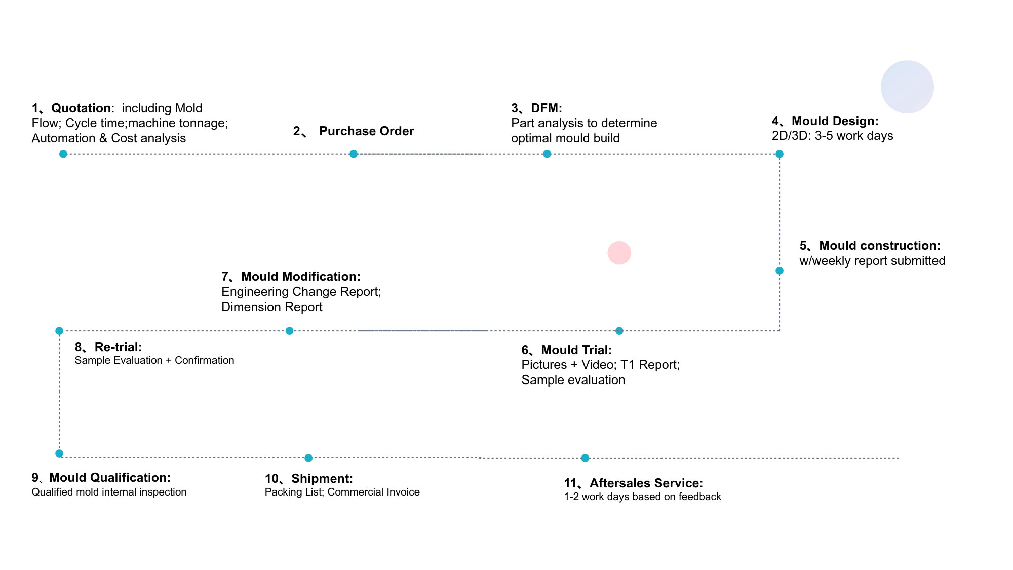
9.4 Order-to-Delivery Timeline Standards
Project Phase Typical Duration Expedited Available
DFM analysis 3-7 days 2-3 days
Mold design and DFM sign-off 7-14 days 5-7 days
Mold fabrication 15-45 days (complexity-dependent) 70% of standard
T0-T3 sampling 5-15 days Not compressible
Small-batch validation 3-7 days Not compressible
Production ramp-up 7-14 days 5-10 days
X. Strategic Value Summary: The Ansix Tech Difference
For clients evaluating headboard gas-assisted molding solutions, the decision to partner with Ansix Tech delivers hard-cost economics supported by technical capability, process control, and lifecycle support.
Key Performance Metrics Summary
Metric Industry Typical Ansix Tech Standard Client Benefit
Material consumption reduction — 20–40% Direct cost savings, lower shipping weight
Cycle time reduction — 30–50% Expanded capacity without capital expenditure
Clamp force requirement Full packing pressure Up to 70% lower Enables smaller, lower-cost machines
Flash at parting line 0.15–0.20mm ≤0.03mm Zero manual deburring
Mold wear life (GF materials) 30,000–80,000 cycles ≥500,000 cycles Extended production runs without rebuilds
Dimensional batch variation (CTQ features) ±0.10–0.20mm ≤0.02mm True part interchangeability
Scrap rate in production 3–5% ≤2.0% Higher yield on every batch
Mold repair lead time 5-10 days ≤24 hours Minimal production disruption
Why Gas-Assisted Molding Matters for Headboard Manufacturing
Lightweighting: Eliminates non-structural mass without compromising strength—lower shipping cost and improved consumer handling.
Surface quality: Through internal gas pressure maintains Class A finished surfaces without sink marks or warpage.
Material efficiency: 20–40% plastic savings delivers immediate environmental and economic benefits.
Why Ansix Tech Beyond Competitors
28 years of gas-assisted molding expertise with proven references across automotive, furniture, appliance, and consumer goods industries.
End-to-end capability from DFM through final assembly —allows single-source project accountability and eliminates interface risk between multiple suppliers.
Dual-shore manufacturing footprint —mainland China for production cost optimization and Vietnam for ASEAN trade agreement access.
Value-based pricing model —Ansix Tech structures commercial terms to align with client outcomes.
XI. Client Engagement: The DFM Deep Dive
Understanding Ansix Tech’s value proposition requires moving beyond claims to tangible demonstration. The recommended starting point for any prospective Headboard Gas-Assisted Molding project is a structured DFM analysis of an existing or in-development component.
During the DFM review, Ansix Tech engineering teams will:
Identify predicted weld line locations and cosmetic risk areas
Map gas penetration paths to confirm material displacement targets the intended thick sections
Recommend gate and gas pin placements positioned for hidden or non-visible surfaces
Assess demolding feasibility and confirm draft angle adequacy
Estimate mold construction cost, lead time, and expected per-shot cycle time
At Ansix Tech, a mold is not a piece of steel—it is a revenue-generating asset. Every mold is designed with production-day maintainability, predictable venting behavior, thermal balance, and ejection robustness engineered from the outset. The result is a tool that arrives on the client’s floor ready for immediate qualification: low flash, high cycle life, and minimal process setup time.
The invitation to prospective clients is simple: provide a 3D model and production volume target. Ansix Tech will deliver a DFM risk profile with anticipated cost and lead time—demonstrating exactly how weld lines, gas blow-through, sink marks, and dimensional instability will be resolved before steel is cut.
For inquiries, DFM consultation, or facility visits, contact Ansix Tech directly.
Phone: +8613530645990 | Email: info@ansixtech.com | Website: www.ansixtech.com
This document is for informational purposes. Specifications subject to engineering review at project initiation. © 2026 Ansix Tech. All rights reserved.
Ansix Tech Co Ltd
If you have any plans related to Headboard Gas-Assisted Molding , you can contact us at any time. We will turn your ideas into reality, let you realize your dreams, and obtain large orders from the market. Our contact information is info@ansixtech.com. Or contact our CTO, mail: stephen@ansixtech.com
#www.ansixtech.com #ansixtech.com #Headboard Gas-Assisted Molding #Headboard Gas-Assisted Molding moulds #Headboard Gas-Assisted Molding injection molding companies #Headboard Gas-Assisted Molding Canopy Mold injection mold companies #Ansix #Ansix moulds #Ansix china #Ansix tech china #Ansix tech company #Ansix facotry #Headboard Gas-Assisted Molding injection molding #Headboard Gas-Assisted Molding injection tools #Headboard Gas-Assisted Molding injection moulds #Headboard Gas-Assisted Molding plastic mould #Headboard Gas-Assisted Molding plastic tools #Ansix Tech #Ansix molds #Ansix injection molding #Ansix mold factory #injection molding Headboard Gas-Assisted Molding #Ansix mold factory #Headboard Gas-Assisted Molding china #Headboard Gas-Assisted Molding molds #injection factory #Headboard Gas-Assisted Molding injection molding #Headboard Gas-Assisted Molding injection molding factory #injection molding company #Headboard Gas-Assisted Molding injection mold companies #Headboard Gas-Assisted Molding#Headboard Gas-Assisted Molding mold limited #Ansix mold china #Ansix companies #Ansix company China #Headboard Gas-Assisted Molding facotry #Ansix Tech #Ansix Tech mould #Headboard Gas-Assisted Molding injection moulding #injection moulding company #Ansix Headboard Gas-Assisted Molding parts injection mold companies #medical injection molding companieschina #Headboard Gas-Assisted Molding china factory #Ansix moulding companies #Ansix molding company #Headboard Gas-Assisted Molding injection moulding facotry #Ansix Tech mold #Headboard Gas-Assisted Molding mould #Headboard Gas-Assisted Molding plastic injection molding #ansix plastic mold #Mold manufacturing #Headboard Gas-Assisted Molding parts manufacturing #Headboard Gas-Assisted Molding plastic parts factory #Headboard Gas-Assisted Molding injection parts mold #Headboard Gas-Assisted Molding PRECISION MANUFACTURING #Headboard Gas-Assisted Molding #China mold #Headboard Gas-Assisted Molding injection moulding china #Headboard Gas-Assisted Molding mould china #china precision mold #mold in china #Headboard Gas-Assisted Molding mold china #Precision molds #High-precision molds #Headboard Gas-Assisted Molding #Injection molds #Headboard Gas-Assisted Molding Factory #Headboard Gas-Assisted Molding Company #Super Large Injection Mold Factory #Large Tonnage Injection Molding Factory #Headboard Gas-Assisted Molding Company #Headboard Gas-Assisted Molding Factory #2800T Injection Molding Factory #3000 Ton Injection Molding #4500 Ton Injection Molding Factory #Large Mold Injection Molding #Large Plastic Mold Injection Molding Factory #Large Injection Mold Manufacturer #Plastic Mold Factory #Injection Mold #Plastic Mold