



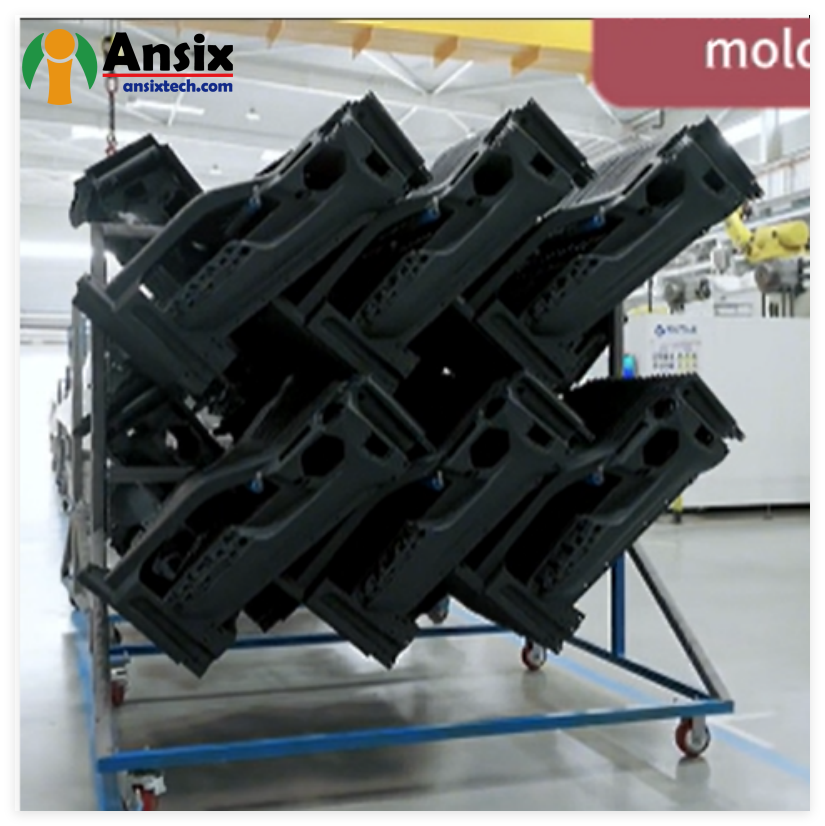
The rear door lower guard panel is made of PP micro-foam molding
The rear door lower guard panel is made of PP micro-Foam Molding

Industry-leading material suppliers such as LyondellBasell have developed specialized PP foam grades (e.g., Hostacom foaming material) that utilize advanced catalyst technology to enhance polymer matrix rheology, delivering high flowability, expanded processing windows, and excellent melt strength for optimal foam cell structure. These materials enable the production of lightweight parts with enhanced surface textures, scratch resistance, and low VOC/emission profiles—critical requirements for automotive interior and exterior trim applications.
PP Foaming Density & MuCell Expansion Ranges
The microcellular foam structure in PP components is characterized by two primary density metrics: material density reduction and expansion ratio.
Density Reduction Capabilities:
Standard range: 8–12% material density reduction through MuCell® technology
Total part weight reduction: 20–30% through optimized foam design
Achievable density reduction: Up to 50% for specific structural foam applications
Typical automotive PP compounds: Processed to structural foams with 30–50% density reduction
Expansion Ratio (Density Ratio):
PC/ABS with nitrogen in MuCell process: 1.29–2.7 expansion ratio
PP with nitrogen in MuCell process: 1.29–3 expansion ratio (where an expansion ratio of up to 2.0 delivers good mechanical performance)
Foam Cell Structure Parameters:
Average cell diameter: < 50 μm (microcellular range)
Cell density: Approximately 8 million cells per cubic centimeter
Bubble size comparison: Physical foaming (MuCell®) yields bubble size < 100 μm; chemical foaming typically yields > 100 μm
Process-Specific Performance Data:
MuCell® process using supercritical fluid (SCF) foaming agent reduces product weight, molding energy, and cycle time while improving foam quality
With optimized parameters, gas permeability flow rate in PP foam material reaches 300–450 mL/min; gas counter pressure application enhances gas permeability to approximately 500 mL/min
Foam cell nucleation and growth replace the traditional packing/holding stage in injection molding, producing low-stress parts with enhanced dimensional stability and significantly reduced warpage
Lightweighting Performance:
Typical weight reduction: 5–20% via microcellular foaming with solid skin/foamed core structure
MuCell® technology achieves density reduction through bubble growth replacing the packing stage, creating uniform shrinkage and predictable, repeatable part geometry
Parts maintain or improve mechanical performance while drastically reducing mass
- Product Introduction & Key Advantages
Product Overview
The rear door lower guard panel is a structurally critical automotive exterior component that protects the lower portion of the vehicle‘s rear door from impacts, road debris, weathering, and corrosion. Manufactured via PP micro-foam injection molding, this component delivers an optimal balance of lightweight construction, impact resistance, dimensional stability, and aesthetic quality.
Key Advantages
Lightweight Construction — The microcellular foam structure achieves 8–12% material density reduction and 20–30% overall part weight reduction compared to solid injection-molded alternatives. This directly contributes to vehicle fuel efficiency and reduced carbon footprint.
Cost Efficiency — The MuCell® process eliminates the traditional packing/holding stage, reducing material consumption by 8–12%, shortening cycle times, lowering clamp tonnage requirements, and enabling the use of cost-effective polyolefin resins without warpage or deformation risks. Total part cost reduction of 10–20% is achievable.
Enhanced Mechanical Properties — The microcellular foam structure (average cell diameter < 50 μm, cell density ~8 million cells/cm³) provides superior impact energy absorption and fatigue resistance compared to solid parts at equivalent weight. Foam core with solid skin structure optimizes stiffness-to-weight ratio.
Dimensional Stability — The foaming process replaces traditional packing with bubble growth, producing low-stress components with uniform shrinkage and highly predictable, repeatable geometry. Warpage and sink marks are significantly reduced.
Sustainability — MuCell® physical foaming uses supercritical nitrogen (N₂) or carbon dioxide (CO₂) as the foaming agent, leaving no chemical residues in the polymer. Finished parts are fully recyclable under their original polymer classification, and the process does not alter the polymer‘s chemical properties. Reduced material consumption and lower energy requirements decrease overall carbon footprint.
Production Process & Efficiency
Process Parameter Value / Capability
Technology MuCell® microcellular foam injection molding
Foaming agent Supercritical N₂ or CO₂ (physical foaming, no chemical residues)
Injection machine range 30T to 4000T fully servo-electric drives
Repeatability precision ±0.1% shot-to-shot consistency
Cycle time reduction 15–30% vs. solid molding
Material consumption reduction 8–12%
All molding machines are networked with MES (Manufacturing Execution System) integration. Process parameters — temperature, pressure, injection speed, cooling time — are locked in MES and modifiable only by authorized engineering personnel. Each batch undergoes first-article and last-article inspection to verify consistency.
Quality Assurance — Process capability is verified on Critical-to-Quality (CTQ) dimensions with CpK ≥ 1.33 before production approval. Every mold undergoes full dimensional reporting before delivery, with key dimensions meeting CpK≥1.33. In-process inspection includes real-time SPC (Statistical Process Control) monitoring with automatic alarms for out-of-control conditions.
Delivery & Lead Times — Standard tooling completion: 10–25 days for simple molds, 25–45 days for medium-complexity, 45–65 days for high-precision multi-cavity molds with expedited options available (20-day compression timeline with validation steps preserved). Rapid prototyping and T0 sampling accelerate time-to-market.
Competitive Cost Control — Cost advantage is driven by four factors: (1) material savings through foaming technology (8–12% reduction in resin consumption per part), (2) shorter cycle times increasing machine utilization, (3) reduced clamp tonnage enabling smaller machine footprints, and (4) DFM-optimized mold design that minimizes secondary finishing operations. Customers typically achieve 10–20% lower part cost versus conventional injection molding.
After-Sales Service Quality — Spare wear components (ejector pins, core inserts) delivered with the mold. Mold maintenance service scheduled at 200k-cycle intervals. Lifetime repair service at cost-based pricing. Technical support response within 24 hours globally.
Summary Table: Product & Production Advantages
Category Specification
Material System PP + GF (10–40%) with MuCell® physical foaming
Foaming Agent Supercritical N₂ or CO₂ — no chemical residues
Injection Machine Range 30T to 4000T fully servo-electric
Weight Reduction 8–12% material density, 20–30% total part weight
Cycle Time Reduction 15–30% vs. solid molding
Mold Tooling Lead Time 10–25 days (simple) / 25–45 days (standard) / 45–65 days (high-precision)
Process Capability CpK ≥ 1.33 on CTQ dimensions
Cost Advantage 10–20% lower part cost vs. conventional molding
Service Model 200k-cycle maintenance interval, 24h technical response
- The Five-Pillar Hard Power Framework
Pillar 1: Hard Power Foundation — Equipment That Builds Customer Confidence
Mold Machining Equipment:
High-Precision Machining: Our 5-axis high-speed CNC machining centers feature 5-axis 5-linkage technology with positioning accuracy of ±0.002 mm and repeat positioning accuracy of ±0.001 mm. This enables the machining of complex contoured surfaces for split lines and parting edges that are smooth, burr-free, and free of witness marks — parts that require no secondary deburring operations. The integrated pentahedral processing technology completes complex surface machining in a single setup, eliminating the dimensional accumulation errors that plague multi-setup approaches.
Precision EDM Wire Cutting: Slow wire EDM systems handle micro-hole and narrow-slot geometries down to 0.03 mm diameter, critical for thin-wall sections and intricate core/cavity features where tool access is restricted.
Value to Customer: Smooth parting lines eliminate customer rework costs. ±0.002 mm precision ensures mold halves mate perfectly, reducing flash (0.03 mm maximum) and eliminating manual deflashing. Single-setup 5-axis machining means faster tool delivery and lower mold costs.
Injection Molding Machine Fleet:
Our press line ranges from 30 tons to 4000 tons clamping force, covering components from micro-precision parts to large-format structural panels. All machines are fully servo-electric drive systems with ±0.1% shot-to-shot repeatability precision — every shot from the first to the hundred-thousandth is dimensionally identical. Closed-loop process control monitors and adjusts temperature, pressure, injection speed, and cooling time in real time.
Value to Customer: From prototyping to high-volume production, we scale capacity without retooling. ±0.1% shot consistency means you receive parts that fit assembly fixtures exactly — no selective fitting, no assembly line rework.
Inspection & Metrology Equipment:
We maintain CMM (Coordinate Measuring Machines) and optical imaging measurement systems. Every mold before shipment undergoes full dimensional report comparison with the original CAD model. CTQ dimensions are validated to CpK ≥ 1.33 before production release. For automotive customers, we meet or exceed IATF 16949 requirements including PPAP (Production Part Approval Process) Level 3 documentation with full dimensional layouts and capability studies.
Value to Customer: CpK ≥ 1.33 on CTQ dimensions means your production line experiences zero dimensional surprises. Full PPAP documentation streamlines your customer approval cycle — we speak the quality language that your QA team expects.
Pillar 2: Mold Manufacturing Core Competitiveness — Specific Metrics That Matter
Customer concerns: mold life, precision, delivery speed, repair cost.
Mold Life Guarantee:
Mold Steel Grade Hardness (HRC) Best Application
P20 28–34 Prototype / low-volume (<100k cycles)
NAK80 36–40 Medium-volume, excellent polishability
H13 48–52 Core inserts, high-wear, >500k cycles
S136 (stainless) 48–52 Cavity inserts, corrosion resistance, mirror finish
2344 / 8407 46–52 High-temperature, high-cycle applications
DC53 58–62 Extreme wear resistance, long-run tooling
Mold life commitment: For glass fiber-reinforced materials (up to 40% GF), guaranteed 500,000 shots. For unfilled/unreinforced materials, guaranteed 1,000,000+ shots. Full material certification reports and heat treatment curves provided with delivery.
Value to Customer: A mold that lasts 500k–1M shots eliminates mid-project tooling replacement costs. Material and heat treatment traceability ensures quality is baked in, not inspected in.
Achievable Tolerances:
Conventional structural components: ±0.05 mm
Precision gears / medical / tight-tolerance parts: ±0.005 mm
All tolerance claims backed by machined and measured samples at T0 stage
Runner/Gate Systems:
Through Moldflow analysis conducted before any steel is cut, we pre-identify weld line locations, air trap zones, and flow imbalances. Based on analysis results, we optimize gate quantity, type (hot runner, cold runner, valve gate), and location for optimal fill balance. Hot runner systems reduce material waste by eliminating cold runner scrap. Valve-gate sequential control enables family mold filling optimization.
Value to Customer: Proper gate placement eliminates cosmetic weld lines on visible surfaces — your part looks perfect straight from the mold. Eliminating air traps prevents burn marks and voids that would otherwise require post-molding rework.
Cooling System Design:
Cooling channel design accounts for up to 70% of cycle time optimization. Our approach uses conformal cooling channels (3D-printed or machined) placed optimally relative to part geometry, combined with mold temperature controllers (water or oil) that maintain cavity/core temperature differentials within 2°C — minimizing differential shrinkage and part warpage. Temperature mapping across the mold ensures uniform cooling rates from gate to flow-end.
Value to Customer: Uniform cooling means your part does not warp. Every part fits its assembly every time. Shorter cooling cycle means lower part cost — and we deliver both.
Standard Delivery Timeline:
Mold Complexity Standard Lead Time Expedited Lead Time
Simple mold 10 days N/A
Medium complexity 25–45 days 20 days (with all validation steps preserved)
High-precision multi-cavity 45–65 days 35 days
Pillar 3: Injection Molding Process Control — Eliminating Customer Quality Concerns
Customer fears: sinks, flash, dimensional instability, batch-to-batch color variation.
Process Standardization:
All molding machines are networked with MES (Manufacturing Execution System). Process parameters — melt temperature, mold temperature, injection pressure and velocity, cooling time, clamp force — are locked in the MES database and only adjustable by authorized engineering personnel. Each production batch undergoes first-article and last-article dimensional and cosmetic inspection, with all data retained for traceability.
Value to Customer: Parameter locks mean no unauthorized operator adjustments. What passed qualification last year passes again today. Traceability means if something ever goes wrong, we identify the root cause in hours, not weeks.
Dimensional Stability Control:
Each mold is equipped with strategically positioned mold temperature controllers (zone-controlled water/oil systems) maintaining cavity/core temperature differentials within 2°C. For a typical structural bracket component, continuous production across three separate weeks shows critical hole-to-hole spacing variation ≤ 0.02 mm. Cavity pressure sensors monitor real-time fill profiles — variations trigger automatic compensation adjustments to packing pressure.
Surface Quality Achievements:
Surface Requirement Achievable Rating / Parameter
Transparent parts (no bubbles, no flow lines) SPI A-1 (mirror finish)
Plated parts (no gas streaks, no flow marks) Gas entrapment eliminated via Moldflow venting optimization
High-gloss painted surfaces Base surface roughness Ra ≤ 0.2 μm
For parts requiring printing/painting operations, we incorporate controlled warpage compensation into the mold design. Printed graphics achieve ±0.1 mm registration accuracy.
Special Material Capabilities (Proven Production Experience):
PC/ABS, PC — Impact grades for interior trim
PPS + 40% GF — High-temperature structural components
PEEK, PTFE/PFA — High-performance engineering grades
PA6 + GF30 — Structural components requiring high strength
PBT, PEI, LCP — Electrical/electronic housings
PPS/LCP — High-flow, high-temperature stable materials
LSR (Liquid Silicone Rubber) — Seals and gaskets
All materials with UL94 flammability ratings up to V-0 for under-hood and electrical housings. UV aging testing completed to 3000+ hours for exterior-grade components with no significant color shift or property degradation.
Value to Customer: You are not limited by our material experience — bring any engineering-grade resin, and we have processed it. One supplier for everything from PC-ABS interior to PEEK under-hood components.
Pillar 4: Full-Lifecycle Service — Reducing Your Management Overhead
This is where many manufacturers fall short. We build it in from Day 1.
Early Engagement (DFM Report):
Before tooling contract signing, we deliver a comprehensive Design for Manufacturability (DFM) analysis report, including:
Parting line location optimization
Draft angle recommendations (minimum 1° per side for textured surfaces, 0.5° for polished)
Wall thickness optimization (uniformity recommendations ±0.1 mm for consistent fill)
Gate location and type recommendations
Ejector pin mark location allowances (areas acceptable for marks vs. visible surfaces requiring hidden or edge ejection)
Shrinkage factor recommendations for PP-based foam formulations (accounting for 8–12% density reduction)
Value to Customer: This report catches design flaws before steel is cut — saving weeks of rework cycles. We translate “draft angle” into “lower mold cost because we need fewer slides.” We translate “ejector mark location” into “cosmetic surfaces protected.”
Sampling and Trial Runs:
T0 through T3 sampling stages with improvement reports at each iteration. Capability for rapid insert changes to evaluate alternate gate designs or cavity configurations without full mold rebuild.
Value to Customer: Lower trial costs. Faster design iterations. We do not charge you to find our mistakes — we find them on our time.
Low-Volume Validation / Pilot Production:
Before full production release, we run 100–500 validation shots, complete with statistical yield analysis and CpK reporting. Production only proceeds when all customer-specified quality gates are met and approved.
Value to Customer: No risk. You approve pilot production results before committing to full-rate manufacturing. We guarantee process capability before the first production part ever ships.
Maintenance and Spare Parts:
Complete set of spare wear components (ejector pins, core pins, wear plates) included with mold delivery
Scheduled mold maintenance service at 200,000-shot intervals
Lifetime repair services available at cost-based pricing (no markup)
Local service coverage for major automotive manufacturing regions
Value to Customer: A planned mold maintenance program means you never face an unplanned shutdown. Cost-based repairs mean no surprises in your tooling budget.
Pillar 5: Differentiated Commitments — Turning Industry Pain Points into Our Guarantees
Common Industry Complaint Ansix’s Commitment (Verifiable)
“My mold is always in repair — production interruptions every month.” Pre-delivery: 2,000-shot aging test with wear report. Post-delivery: Three-year mold structure warranty (excluding normal wear components).
“Flash everywhere — I pay operators to manually trim every part.” Parting line precision: ±0.005 mm machining tolerance across split surfaces. Self-locking clamp force compensation ensures flash ≤0.03 mm per cavity — no manual trimming required.
“Every batch dimensions are different — assembly line constantly adjusts.” In-mold temperature sensors, cavity pressure transducers with closed-loop feedback to machine controller — real-time adjustment of pack pressure. Same dimensions, every batch, every shift.
“Mold repair takes weeks — my production line stops.” In-house EDM and CNC electrode manufacturing centers. Mold repair never leaves our facility. Standard repairs (welding/pin replacement) complete in 24 hours.
Our Philosophy:
“For us, a mold is not a block of steel — it is a money printer for our customer. We design for production: controlled flow balance, proper venting, temperature uniformity across the cavity. When our mold arrives on your line, it runs. No debugging. Minimal flash. Long life.”
- Project Lifecycle & Customer Value Delivery
Ansix Tech provides end-to-end PP micro-foam molding services: from design and prototyping through high-volume production and just-in-time delivery.
Phase 1: Project Initiation & Design Engineering
DFM (Design for Manufacturability) Analysis:
Part geometry review against PP foam injection requirements
Shrinkage prediction accounting for 8–12% material density reduction through MuCell process — standard PP foam shrinkage factors adjusted for foam behavior to eliminate warpage
Gate location, runner layout, venting placement optimized via Moldflow simulation
Draft angle recommendations for PP material (typically 0.5–1.5° per side depending on surface texture)
Wall thickness uniformity recommendations (±0.1 mm range for consistent foam distribution)
Ejector pin placement review for cosmetic surface protection
Material Selection & Validation:
PP base resin selection based on melt flow index (MFI), flexural modulus, impact performance
GF content range: 10% to 40% depending on stiffness requirements
Foaming technology: MuCell® physical foaming using supercritical N₂ (primary) or CO₂ — no chemical residues
Additive package: UV stabilizers, color masterbatch, coupling agents
Flammability rating: UL94 V-0 compliant for specific applications
Validation: Tensile, flexural, and impact testing before production approval
Phase 2: Mold Design, Engineering & Tool Manufacturing
Mold Engineering Priorities for Mass Production:
Steel selection based on production volume and material (see steel grade table in Pillar 2)
Cooling system design with zone-controlled water/oil circuits — critical for PP foam molding where temperature uniformity influences bubble growth and skin formation
Runner and gate system balanced for consistent fill across all cavities
Venting placement to eliminate gas entrapment during foam expansion
Ejector system design for foam parts — larger ejection surface area required due to reduced structural rigidity vs. solid PP parts
Mold base design for automated part extraction (robotic handling integration)
Mold Manufacturing Process:
5-axis high-speed CNC roughing to near-net shape
5-axis finishing with ±0.002 mm precision on critical contours and parting surfaces
EDM (electrical discharge machining) for fine features and small-radius details
Precision grinding for flat surfaces and mating interfaces
Heat treatment per material specification (H13, S136, DC53 to required HRC ranges)
Polishing to SPI A-1 through C-3 ratings depending on cosmetic requirements
Laser marking of cavity identification and mold serialization
Final assembly with fitted guide pins, bushings, and locking mechanisms
Phase 3: Product Validation & Pilot Production
T0 – T3 Sampling Stages:
First samples (T0) — functional check, basic dimensions, gate vestige evaluation
Sample inspection report with full dimensional layout against 2D drawing
Foam quality evaluation: cross-section microscopy for cell size and density uniformity
Cosmetic inspection under lighting conditions matching final assembly environment
Mechanical property validation (if specified): flexural modulus, impact strength, tensile performance
Process Optimization:
Design of Experiments (DOE) for critical parameters: melt temperature, mold temperature, injection velocity, N₂ supercritical fluid concentration, gas counter pressure
Definition of “golden recipe” process window (nominal / high / low bounds)
MES parameter locking for production release
Pilot Production (Pre-Production Validation):
100–500 low-volume validation run on production-intent tooling
CpK analysis on CTQ dimensions — requirement CpK ≥ 1.33
First article inspection (FAI) complete report
Yield analysis: cosmetic and dimensional reject rates
Customer approval gate before mass production
Phase 4: Mass Production
Production Infrastructure:
30T to 4000T fully servo-electric injection presses
In-machine robotic part extraction
Automated gate trimming (where required)
In-line vision inspection for critical dimensions and cosmetic defects
Packaging automation: part stacking, counting, boxing, labeling
Quality System:
IATF 16949 certified production environment
Real-time MES monitoring: cycle time, scrap rate, OEE tracking
SPC (Statistical Process Control) charts for all CTQ characteristics
Sample inspection frequency determined by customer specification (typically 1–5 pieces per shift or per run)
CPK maintained ≥1.33 through process capability studies
Phase 5: Just-in-Time Delivery
Logistics Capabilities:
Warehousing capacity supporting safety stock levels
Dedicated delivery fleet for regional customers
Global shipping partnerships for international distribution
Real-time inventory visibility via customer portal
Pack-to-order capability for multi-part assembly kits
Phase 6: After-Sales Support
Technical Support:
24-hour response time for technical inquiries (global time zones covered)
Root cause analysis reports for any quality incidents
Corrective action / preventive action (CAPA) documentation
Mold Maintenance:
Scheduled maintenance at customer facility or return-to-Ansix
Complete spare parts inventory for all active tooling
Lifetime repair pricing at cost-based rates (no mark-up)
Continuous Improvement:
Annual quality review meetings
Cost reduction proposals based on production data analysis (reduced cycle times, material optimization, improved yields)
Engineering change management support
- Cost Reduction Capabilities — The Ansix Advantage
Ansix Tech reduces customer‘s hard costs through four specific levers:
- Material Cost Reduction (8–12% savings):
MuCell® microcellular foaming reduces material density by 8–12% compared to solid injection molding. For high-volume automotive components, this material saving translates directly to reduced per-part resin cost. At typical automotive volumes of 100,000 to 500,000 units annually, 8–12% resin savings delivers five- to six-figure annual cost reduction. PP foam parts are fully recyclable — regrind can be reintroduced into production without property degradation, further reducing virgin material consumption.
- Cycle Time Reduction (15–30% faster):
MuCell eliminates the traditional packing/holding stage — bubble growth replaces pressure packing. Cooling time is also reduced due to lower thermal mass of foam structure. Net effect: 15–30% faster cycle times. For a high-cavitation mold running around the clock, faster cycles mean higher daily output from the same press — lower cost per part without additional capital investment.
- Lower Clamp Tonnage — Smaller Machine Footprint:
Foam injection requires significantly lower clamp force than solid injection. At weight reduction levels of 20–30%, clamp tonnage requirement drops correspondingly. Less tonnage means smaller (less expensive) injection presses, lower energy consumption, and reduced machine maintenance costs.
- Eliminated Secondary Operations (0% flash = 0% manual deflashing):
±0.002 mm parting surface precision and ±0.03 mm maximum flash means no manual deflashing required. For high-volume production, eliminating manual trimming operations typically saves $0.05–$0.15 per part in direct labor — and eliminates the quality risk of operator-induced damage.
- Reduced Assembly Scrap (CpK ≥ 1.33 = 100% fit):
When every part meets the same critical dimensions (CpK ≥ 1.33), assembly line changeovers are eliminated. No selective fitting. No rework of out-of-tolerance parts. Scrap rates in downstream assembly approach zero.
- Extended Tool Life (Lower Replacement Cost):
500k–1M shot tool life means no mid-project mold replacement. Capital cost amortized over higher total output = lower depreciation cost per part.
Conclusion
For a manufacturer like Ansix Tech, delivering customer satisfaction and industry leadership in PP micro-foam molding for rear door lower guard panels requires discipline across every phase of the product lifecycle:
Technical competence — understanding the physics of MuCell® foam nucleation, cell growth, and the relationship between process parameters and final part properties.
Manufacturing capability — precision mold-making equipment, wide press range, and fully instrumented process control systems that guarantee shot-to-shot consistency.
Process discipline — documented standard operating procedures, locked parameters, and statistical process control that customers can audit and trust.
Cost transparency — showing customers exactly how we save them money through material reduction, cycle time reduction, eliminated secondary operations, and longer tool life.
Supply chain integration — delivering on time, communicating proactively, and supporting the product throughout its lifecycle.
Continuous improvement — reviewing every project’s performance data and feeding lessons back into design guidelines, process standards, and customer recommendations.
When these elements come together, the result is a customer relationship built on trust and demonstrated value — not just a transaction for molded plastic parts. The rear door lower guard panel becomes a showcase of what modern microcellular foam molding can achieve when expertise and execution align.


Ansix Tech Co Ltd
If you have any plans related to The rear door lower guard panel is made of PP micro-foam molding , you can contact us at any time. We will turn your ideas into reality, let you realize your dreams, and obtain large orders from the market. Our contact information is info@ansixtech.com. Or contact our CTO, mail: stephen@ansixtech.com
#www.ansixtech.com #ansixtech.com #The rear door lower guard panel is made of PP micro-foam molding #The rear door lower guard panel is made of PP micro-foam molding injection molding companies #The rear door lower guard panel is made of PP micro-foam molding Canopy Mold injection mold companies #Ansix #Ansix moulds #Ansix china #Ansix tech china #Ansix tech company #Ansix facotry #The rear door lower guard panel is made of PP micro-foam molding injection molding #The rear door lower guard panel is made of PP micro-foam molding injection tools #The rear door lower guard panel is made of PP micro-foam molding injection moulds #The rear door lower guard panel is made of PP micro-foam molding plastic mould #The rear door lower guard panel is made of PP micro-foam molding plastic tools #Ansix Tech #Ansix molds #Ansix injection molding #Ansix mold factory #injection molding The rear door lower guard panel is made of PP micro-foam molding#Ansix mold factory #The rear door lower guard panel is made of PP micro-foam molding china #The rear door lower guard panel is made of PP micro-foam molding molds #injection factory #The rear door lower guard panel is made of PP micro-foam molding injection molding #The rear door lower guard panel is made of PP micro-foam molding injection molding factory #injection molding company #The rear door lower guard panel is made of PP micro-foam molding injection mold companies #The rear door lower guard panel is made of PP micro-foam molding Tooling #The rear door lower guard panel is made of PP micro-foam molding mold limited #Ansix mold china #Ansix companies #Ansix company China #The rear door lower guard panel is made of PP micro-foam molding facotry #Ansix Tech #Ansix Tech mould #The rear door lower guard panel is made of PP micro-foam molding injection moulding #injection moulding company #Ansix The rear door lower guard panel is made of PP micro-foam molding parts injection mold companies #medical injection molding companieschina #The rear door lower guard panel is made of PP micro-foam molding china factory #Ansix moulding companies #Ansix molding company #The rear door lower guard panel is made of PP micro-foam molding injection moulding facotry #Ansix Tech mold #The rear door lower guard panel is made of PP micro-foam molding mould #The rear door lower guard panel is made of PP micro-foam molding plastic injection molding #ansix plastic mold #Mold manufacturing #The rear door lower guard panel is made of PP micro-foam molding parts manufacturing #The rear door lower guard panel is made of PP micro-foam molding plastic parts factory #The rear door lower guard panel is made of PP micro-foam molding injection parts mold #The rear door lower guard panel is made of PP micro-foam molding PRECISION MANUFACTURING #The rear door lower guard panel is made of PP micro-foam molding #China mold #The rear door lower guard panel is made of PP micro-foam molding injection moulding china #The rear door lower guard panel is made of PP micro-foam molding mould china #china precision mold #mold in china #The rear door lower guard panel is made of PP micro-foam molding mold china #Precision molds #High-precision molds #The rear door lower guard panel is made of PP micro-foam molding #Injection molds #The rear door lower guard panel is made of PP micro-foam molding Factory #The rear door lower guard panel is made of PP micro-foam molding Company #Super Large Injection Mold Factory #Large Tonnage Injection Molding Factory #The rear door lower guard panel is made of PP micro-foam molding Company #The rear door lower guard panel is made of PP micro-foam molding Factory #2800T Injection Molding Factory #3000 Ton Injection Molding #4500 Ton Injection Molding Factory #Large Mold Injection Molding #Large Plastic Mold Injection Molding Factory #Large Injection Mold Manufacturer #Plastic Mold Factory #Injection Mold #Plastic Mold