


Lumbar Support Backrest Mold
FEATURES
Hard Infrastructure: The Foundation That Builds Customer Trust
Your confidence in any manufacturing partner begins with the equipment and facilities behind the promise. Ansix Tech operates four strategic production bases across China and Vietnam, with a total building area of approximately 200,000 square meters, employing over 1,200 people including more than 200 dedicated design engineers. Our infrastructure is not merely a collection of machines—it is a precision ecosystem engineered to deliver consistency, accuracy, and scalability.
A. Mold Machining Equipment: Precision That Eliminates Post-Processing
We have achieved an automated machining ratio of 70%, with a cumulative track record of over 30,000 mold sets built since our founding. Our mold manufacturing capabilities center on advanced machining technologies that directly translate to superior part quality and reduced finishing costs for you.
Five-Axis High-Speed Machining Centers: Our facility is equipped with high-speed CNC machines from world-class manufacturers, delivering machining accuracy up to ±0.002mm with surface roughness as low as Ra 0.15μm, capable of machining hardened steel up to 60HRC. For lumbar support backrest components, which often feature complex free-form surfaces and ergonomic contours, this precision means your product‘s parting lines will be smooth and flash-free right out of the mold, eliminating costly manual deburring operations.
-
Mold Description
Product Materials:
PP PP+EPDM
Mold Material:
S136ESR
Number of Cavities:
1
Glue Feeding Method:
COLD runner
Cooling Method:
Water cooling
Molding Cycle
32.5s
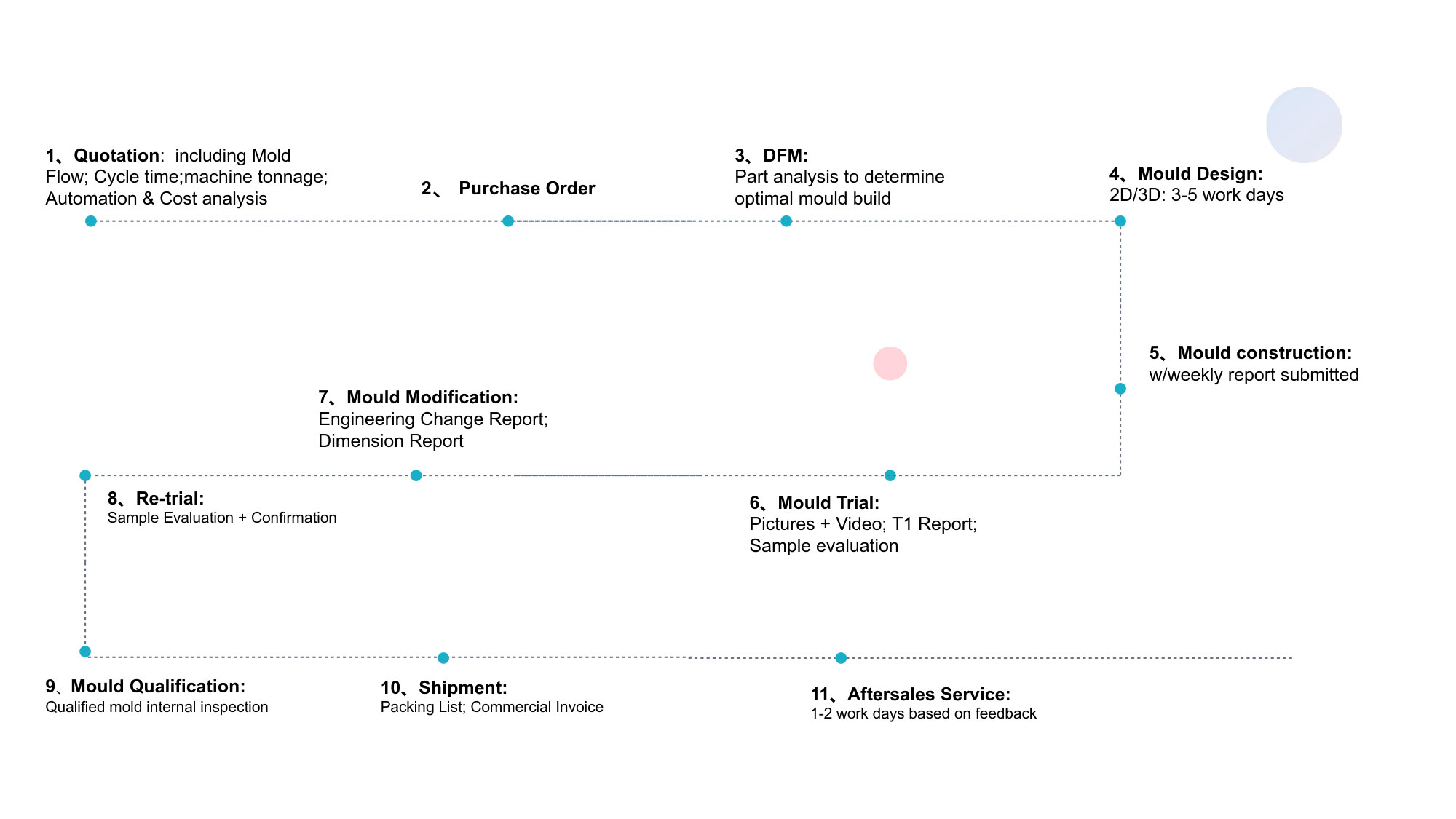
- The mold manufacturing process and product material selection
Wire EDM and Sinker EDM: Using Wire EDM capabilities with accuracy down to ±0.002mm and surface finish Ra 0.05μm, we can machine intricate contours, sharp internal corners, and narrow slots as fine as 0.03mm that milling cannot reach. This capability is particularly critical for lumbar support backrest molds that incorporate fine features, vent channels, and precise insert locations—ensuring your thin-wall sections remain structurally sound without deformation risk.
Precision Grinding: Our grinding capabilities achieve accuracy to ±0.001mm on flat, cylindrical, and profile grinding operations, ensuring perfect fitment of inserts, slides, and mold bases. The result is a mold that closes with micrometer-level precision, eliminating the micro-gaps that cause flash and scrap.
-
Injection Molding Machine Fleet: Scale That Grows With You
Ansix Tech operates a total of 260 injection molding machines with tonnage ranging from 30 tons to 2800 tons. This comprehensive range ensures we can serve applications from small precision components to large-format backrest panels, all under one roof with consistent quality standards.
All-Servo Electric and Hybrid Machines: Our machine park features all-servo electric drive systems that deliver stable repeatability with shot-to-shot accuracy of ±0.1%, ensuring that when you transition from prototype trial to full mass production, every shot replicates the quality of the first. This consistency directly reduces your inspection costs and downstream assembly rejections.
C. Quality Inspection Equipment: Verification You Can Trust
Quality is not negotiable in automotive seating applications, where safety, comfort, and durability are paramount. Our metrology arsenal includes Coordinate Measuring Machines (CMMs) with measurement accuracy within ±0.5μm, vision measuring systems for complex geometry inspection, and high-resolution computed tomography (CT) systems for non-destructive internal defect detection. Every mold we deliver undergoes a full dimensional inspection before shipment, with critical dimensions documented to achieve Cpk ≥ 1.33 for production-ready qualification.
II. Mold Manufacturing Core Competencies: Speaking the Language of Customer Value
The technical specifications of your lumbar support backrest mold—material selection, tolerance capabilities, cooling design, gate configuration—are ultimately meaningless unless they translate to real benefits for your business. Here is how we convert technical expertise into customer advantage.
A. Mold Materials: Matching Steel to Strategy
Selecting the right mold steel determines 70% of your total tooling cost and directly impacts your production uptime and maintenance frequency. Wrong material choices can lead to premature wear, part defects, and unplanned downtime that disrupts your supply chain. We apply a science-based material selection framework that aligns steel properties with your production volume, polymer type, and cosmetic requirements.
Material Hardness (HRC) Primary Application Customer Value Delivered
P20 30-36 Prototypes, low-volume production (<500k cycles) Lowest upfront investment for initial market validation
718 / 1.2738HH 38-42 High-volume automotive interior, Class-A surfaces Balance of durability (1.2M+ cycles) and polishability—ideal for visible backrest surfaces requiring ≤Ra 0.05μm
NAK80 40-43 High-gloss, mirror-finish components Pre-hardened (HRC40), eliminates heat treatment processing, reducing mold delivery time by 30% while delivering 5x longer life than P20 in glass-filled applications
S136 (1.2083) 48-52 Corrosive plastics, transparent/medical components Extreme corrosion resistance—in PVC injection, lifetime is 3x longer than NAK80. Achieves mirror polish to Ra≤0.01μm for optical-grade transparent backrest elements
H13 / 2344 45-50 High-temperature engineering resins, glass-filled materials Superior high-temperature and wear resistance—maintains structural integrity under thermal cycles exceeding 600°C
For lumbar support backrest molds processing glass fiber-reinforced materials such as PA6+GF30 or PPS+40%GF, we guarantee 500,000 mold cycles minimum. For unreinforced engineering thermoplastics, our molds deliver over 1,000,000 cycles. Each mold is accompanied by full material certification reports and heat treatment curves for complete traceability.
B. Machining Tolerance: From Microns to Manufacturing Stability
Your lumbar support backrest components require dimensional consistency across millions of production cycles. ANSIX Tech routinely holds machining tolerances of ±0.002mm on critical mold features, verified through CMM inspection. For your production parts, we translate this mold precision into achievable in-mold tolerances of ±0.05mm for standard structural components and ±0.01mm for precision-fit elements such as hinge bosses and locating features.
This precision directly eliminates assembly fitment issues, reduces your need for secondary sizing operations, and ensures your final product meets automotive OEM specifications from first article through to millionth unit.
C. Mold Architecture: Tailored Solutions for Every Application
Each mold architecture delivers distinct customer benefits. Our design team collaborates with you to select the optimal configuration based on your production volume, part geometry, and cost targets.
Hot Runner Systems: For high-volume production runs of lumbar support backrest components, hot runner systems reduce material waste by 30–50% and shorten molding cycles by 15–30% compared to cold runner designs. Although initial tooling investment is higher (typically 30–80% above cold runner costs), the payback period is measured in months for mass production programs. Moreover, hot runner systems eliminate runner regrind variability, ensuring consistent melt properties shot after shot.
Cold Runner Configurations: For smaller production volumes or geometry where runner waste is manageable, cold runner molds offer lower upfront cost and simpler maintenance, making them the economical choice for prototype runs or low-to-medium volume programs.
Family Molds and Multi-Cavity Layouts: When your lumbar support assembly consists of multiple plastic components, we can design family molds that produce all parts in a single shot, eliminating assembly line kitting and reducing work-in-process inventory.
Overmolding Solutions: Many modern lumbar support systems integrate arching elements molded directly to wire carriers or frames within a single molding tool. Ansix Tech has extensive experience with overmolding applications, integrating metal reinforcement structures into plastic backrest components without secondary assembly operations. This consolidated approach reduces assembly time, eliminates fasteners, and improves product reliability.
D. Gate and Runner Design: Preventing Defects Before Molding Begins
Improper gate placement is the single most common cause of weld lines, gas traps, sink marks, and dimensional instability. Using comprehensive mold flow analysis, we simulate polymer behavior inside the cavity before any steel is cut, identifying optimal gate locations that achieve balanced fill, eliminate weld lines, and minimize internal stress.
Through mold flow analysis, we evaluate critical parameters including fill time progression, weld line location and severity, air entrapment positions, volumetric shrinkage distribution, and pressure drop across the cavity. For a 1+1 cavity arrangement (left and right lumbar components in a single tool), this analysis ensures both cavities fill simultaneously, eliminating part-to-part variation.
This upfront simulation investment pays dividends: reduced trial iterations (we average just 2 mold trails per project), shorter time-to-production, and defect-free first articles.
E. Cooling System Design: Shorter Cycles, Better Parts
Cooling typically represents 60–70% of the total injection molding cycle time. For lumbar support backrest components with complex rib structures and varying wall thicknesses, differential cooling leads to warpage, sink marks, and extended cycle times.
Our cooling system design incorporates conformal cooling channels where justified by ROI, turbulent circuit design for maximum heat transfer efficiency, balanced cooling loops that maintain uniform temperature across all cavities, and mold temperature controller integration for zone-specific regulation. We maintain core/core cavity temperature differentials within 2°C, ensuring uniform shrinkage and minimizing post-mold distortion. Balanced circuits and turbulent flow design achieve optimal heat transfer. For you, this means shorter cycle times (higher output per machine), reduced scrap from warpage, and parts that arrive in spec and stay in spec through temperature fluctuations.
F. Ejection System Design: Flawless Release Without Deformation
Incorrect ejection pin placement distorts thin-wall backrest features, leaving visible witness marks that require cosmetic rework—or worse, rejecting otherwise good parts. We analyze ejection pin placement to distribute forces evenly, selecting pin diameters and placement based on specific pressure calculations to avoid marking Class-A surfaces. For large backrest panels, we integrate air ejectors and stripper plates to provide uniform lift-off force, eliminating part deformation. This attention to ejection design means your parts exit the mold ready to proceed directly to assembly—no rework, no finishing, no delays.
G. Delivery Standards: Predictable Timelines You Can Plan Around
Time-to-market pressure is relentless. Before tooling steel is cut, we provide comprehensive DFM reports that identify optimal draft angles, wall thickness distributions, gate locations, and allowable ejector pin mark positions. This upfront analysis eliminates the hidden Cost of Poor Quality (COPQ) that arises only after production begins.
For simple prototype molds, we deliver in as few as 10 days. For standard production molds requiring engineering plastics and glass-filled materials, our typical lead time ranges from 25 to 45 days. For expedited projects with sufficient design maturity, we can compress delivery to 21 days while maintaining full process validation—never compromising the verification steps that ensure production readiness.
III. Injection Molding Process Control: Eliminating Quality Anxiety Before It Starts
Your greatest concerns as a production manager or procurement leader are centered on quality consistency: What if dimensions drift between batches? What if flash increases scrap rates? What if batches show color variation? Ansix Tech‘s injection molding capabilities are engineered to eliminate these anxieties through scientific molding methodology and Industry 4.0 connectivity.
A. Process Standardization: Locking in Quality Across Every Shot
All our injection molding machines are networked to a Manufacturing Execution System (MES) that locks down all critical production parameters—including melt temperature, injection pressure, injection velocity, hold pressure, holding time, cooling time, and screw recovery parameters. Adjustments require engineer-level authorization with full e-signature change logging.
This is not a theoretical capability. In a documented injection molding program suffering from 20% scrap rates due to part deformation, a combined approach of cost-justified design of experiments and artificial neural network optimization reduced scrap rates to 0% and sustained improvement through a one-month industrial validation. At Ansix Tech, we apply similar scientific molding principles to every customer program.
Control limits are established through screening design of experiments that identify the full process window, with nominal, high, and low boundaries programmed directly into the HMI and MES alarm systems. First-article and last-article samples from every batch are sealed and archived for traceability, with CPK≥1.33 verified on critical-to-quality characteristics before serial production begins.
B. Dimensional Stability: Eliminating Batch-to-Batch Variation
Dimensional variation between production batches is the silent killer of automotive supply chain reliability. Our approach to dimensional control is multi-layered.
We integrate ultrasonic thickness sensors and in-mold cavity pressure/temperature sensors that provide real-time feedback on wall thickness consistency and filling characteristics. For high-precision requirements, we integrate closed-loop temperature control systems that achieve tolerances as tight as ±0.02mm, subject to material-specific evaluation.
Multi-zone temperature controllers maintain mold surface temperature uniformity within ±5°C across the entire cavity surface. For thin-wall lumbar support components, we maintain melt temperature stability within ±1.5% of target. For transparent or high-gloss parts, we maintain hot runner temperature control within ±1°C to prevent localized overheating and material degradation.
Statistical Process Control monitors all critical parameters through continuous production. For a typical lumbar support backrest component, we can demonstrate that key hole-to-hole spacing variability stays within ±0.02mm across three production runs conducted over a one-week period, ensuring your seating systems assemble correctly every time without adjustment.
C. Surface Quality and Appearance Specifications
Different lumbar support applications demand different cosmetic standards.
For Class-A surfaces visible to the end user, we achieve mirror finishes with surface roughness Ra≤0.05μm using NAK80 or S136 mold steels with appropriate polishing processes.
For textured leather-grain surfaces common in automotive interiors, our pre-etching and texturing processes replicate grain patterns with fidelity exceeding 95%, eliminating the visible color sheen variation that plagues inferior molds. We collaborate directly with graining suppliers to specify grain number and etch depth, ensuring consistent texture transfer across every molded part.
For paint-ready surfaces, we mold components with surface defects entirely absent—no gas streaks, no flow marks, no splay. For electroplating or vacuum metallization applications requiring flawless substrate finish, we provide parts with cosmetic-grade surfaces that accept metal deposition without pinholes or adhesion failures.
For clear/transparent components such as backrest trim rings or indicator windows, we achieve bubble-free, flow-mark-free molding through carefully optimized injection profiles and venting strategies, with S136 mold steel delivering 200万 mold cycles without corrosion while maintaining ≥92% light transmittance.
D. Special Material Processing Expertise
Lumbar support backrest systems utilize a wide range of engineering thermoplastics. Ansix Tech maintains extensive process data for both commodity and high-performance resins:
Material Category Examples Key Processing Considerations
Standard Engineering PC/ABS, PP, PC, ABS Broad process windows, cost-effective
Glass-Fiber Reinforced PA6+GF30, PBT+GF30, PP+GF35 Requires high-wear-resistant steels (H13, 2344), abrasive fillers accelerate mold wear
High-Performance PEEK, PEI, PPS+40%GF, LCP High-temperature processing (350–400°C), requires H13 hot work steel, specialized thermal management
High-Temperature PPS, PEI Crystallinity control critical for dimensional stability, anisotropic shrinkage from fiber orientation
Flame-Retardant FR grades of PC/ABS, PBT, PA6 UL94 V-0 compliance, specific mold venting for outgassing
Liquid Silicone Rubber LSR Cold runner systems, precise shot volume control
For glass-fiber reinforced materials, we design mold steels and processing conditions specifically to minimize fiber breakage—preserving fiber length maximizes mechanical performance. For flame-retardant materials requiring UL94 V-0 compliance, we tailor mold venting strategies to facilitate outgassing without compromising burn ratings.
Where justified by production volume, we can recommend materials that reduce part weight and material consumption. Technologies such as micro-cellular foam injection molding can reduce part weight by 10–15% without compromising mechanical performance, while physical foaming processes use no chemical additives, minimizing residues and lowering both material costs and energy consumption.
IV. Full-Service Lifecycle Support: Reducing Your Management Overhead
Managing a global supply chain means jugeting multiple vendors for design, prototyping, tooling, production, secondary operations, and logistics. Each additional vendor introduces communication gaps, quality variability, and coordination overhead. Ansix Tech’s integrated platform eliminates this fragmentation.
A. Early Engagement Through DFM Reports
We begin adding value before any commitments are made. When you share preliminary part designs, our engineering team conducts a comprehensive Design for Manufacturability (DFM) analysis that directly reduces your production risk.
Each DFM report includes material grade recommendations, optimal wall thickness ranges for fill and cool performance, draft angle specifications for reliable ejection without surface damage, gate location options indicating allowable witness mark positions, ejection system design and ejector pin location allowances, cooling system layout for cycle time optimization, and identification of potential molding defects with mitigation strategies.
DFM reports serve as a critical bridge between your product engineers and our molding engineers, especially when product design is still maturing. By addressing manufacturability issues before tooling steel is cut, we prevent downstream problems that become expensive and time-consuming to correct once production is underway. This early engagement eliminates the hidden cost of poor quality that emerges only after line trials.
B. Mold Flow Analysis: Seeing the Future Before Molding Begins
We leverage advanced mold flow analysis software to simulate the entire injection molding process before manufacturing the tool, substantially reducing both development time and risk.
Our analysis evaluates fill time and fill pattern to predict short shots or hesitation marks, weld line location and severity with implications for structural integrity, air entrapment zones requiring venting modifications, volumetric shrinkage distribution to anticipate warpage and sink, pressure drop across the cavity to ensure adequate packing, cooling performance to validate cycle time estimates, and fiber orientation in glass-filled materials for anisotropic property prediction.
For gas-assisted injection molding applications common in lumbar support components requiring hollow or semi-hollow structures, mold flow analysis optimizes gas injection location, gas injection timing, plastic shot volume, delay time, and gas pressure holding profile, reducing the need for multiple physical trials.
With mold flow analysis, what used to require multiple tooling iterations can now be resolved in software, shortening your development timeline by weeks while delivering a mold that is ready for high-volume production on Trial #2.
C. Systematic Mold Validation Protocol
We never ship a mold until it has been proven. Our mold validation process eliminates the risk of discovering issues only after the tool arrives at your facility.
T0 Trial (First Shot): First molding trial evaluates basic cavity filling, ejection function, and presence of major defects such as short shots or severe flash.
T1 Trial (Design Optimization): Following initial design modifications identified in T0, this trial optimizes process parameters, verifies cosmetic quality, and confirms dimensional conformance.
T2 Trial (Production Validation): Continuous production run of 200–500 parts for capability analysis—dimensional measurement, CPK calculation on critical features, visual inspection per agreed cosmetic standards, and functional assembly verification using your mating components.
T3 Trial (Ramp-Up Confirmation): Final verification of stable production at target cycle time with qualified operators, full documentation package preparation, and shipment approval.
Only after passing this validation protocol does your mold ship. This rigorous approach eliminates the costly surprise of mold trials on your production floor.
D. Small-Batch Pre-Production Verification
Rather than committing to full production before process validation is complete, we offer ramped approach of 100–500 shot pre-production run. This phase validates yield rate, confirms CPK on critical dimensions, optimizes cycle time for your specific machine and facility conditions, and provides parts for your internal assembly trial and production approval.
We do not declare full production readiness until statistical process control data confirms stability and quality targets are met. Your first production batch runs with full confidence.
E. Maintenance, Spares, and Service
Long-term mold performance is assured through our comprehensive after-sales support. Every mold ships with a complete set of spare consumable components—including ejector pins, core pins, and any wear-prone inserts—so that minor repairs do not become supply interruptions.
At 200,000-cycle intervals, we recommend preventive maintenance that includes cleaning of vent and cooling channels, surface inspection for wear, measurement of critical dimensions, and replacement of consumable components. We do not merely respond to failures; we anticipate and prevent them. When repair is required, our in-house electrode manufacturing and EDM facilities mean the mold never leaves our control. Standard repairs—steel welding, insert replacement, cooling channel clearing—are completed within 24 hours.
V. Differentiated Competitive Advantages: Directly Addressing Your Pain Points
Where conventional suppliers leave you guessing, Ansix Tech provides explicit, verifiable commitments that address the most common customer frustrations.
A. Comparing Ansix Tech Against Common Industry Shortcomings
Customer Frustration Conventional Supplier Response Ansix Tech Solution
Mold wears prematurely, causing unplanned downtime and order delays Passive response: “Wear is expected after X cycles. Here‘s the repair quote.” Proactive validation: 2,000-cycle accelerated wear test before shipment. We deliver a full wear report and provide a three-year structural warranty on the mold frame (normal consumable wear from production excluded).
Flash on parts requires costly manual deburring, increasing per-part labor cost “Adjust your machine parameters” Zero-flash guarantee: We machine parting lines to fit within 0.005mm clearance, integrate self-locking clamp force compensation, and document that flash remains within 0.03mm across all production cycles—eliminating secondary deburring operations.
Dimensions change between batches, causing assembly line headaches “Material supplier changed their batch” Active compensation: Ultrasonic wall thickness sensors provide real-time feedback, automatically adjusting injection pressure to compensate for viscosity variation. For high-precision programs, in-mold cavity pressure and temperature sensors close the control loop, holding hole-to-hole positioning within ±0.02mm across all batches and shifts.
Mold repair takes too long, extending downtime “We have to send out specialty components. Estimate: two weeks.” In-house rapid response: Our internal electrode manufacturing and EDM departments mean repairs never leave our facility. Standard steel welding or insert replacement is completed within 24 hours. Expedited air freight delivery of repaired tooling available for urgent situations.
Communication delays between design, mold making, and production teams “I‘ll have to transfer you...” Single point of accountability: One project manager, one quality team, one facility. Our integrated platform eliminates the finger-pointing and information loss that fragment projects.
B. The Ansix Tech Cost Advantage: Turning Process Optimization Into Measurable Savings
We have achieved material, process, and efficiency optimization that translates directly to lower per-part cost for you—not by sacrificing quality, but by eliminating waste.
Material Optimization: For programs with high material consumption, we evaluate alternative resin selections from the same or higher performance class. Where justified, we replace standard ABS with PP+20% GF for 18% raw material cost reduction while achieving 30% higher tensile strength—subject to design-specific validation. For flame-retardant grades, we optimize wall thickness and geometry to reduce gram-per-part consumption without compromising UL94 V-0 rating.
Process Efficiency: Our scientific molding methodology identifies the minimum acceptable cycle time required to achieve dimensional stability, not a one-size-fits-all setting. For a typical lumbar support backrest component, this means cycle times as much as 25% shorter than industry average without sacrificing quality.
Waste Reduction: Hot runner system implementation where economically justified reduces runner scrap by 30–50%. For cold runner tools, we optimize runner geometry to minimize material waste while ensuring balanced cavity filling.
Automation Integration: For programs with sufficient volume, we design molds for pick-and-place robot integration, eliminating manual part removal, increasing throughput, and reducing labor cost per part.
Consolidated Purchasing: By sourcing mold steel, machine components, metrology equipment, and resin through our global supply network, we reduce input costs compared to smaller competitors—savings we pass on to you.
C. Packaging, Logistics, and Rapid Delivery
The last step in any manufacturing solution is getting quality product from our dock to your assembly line without damage or delay.
Our standard packaging employs anti-static EPE layered packaging for electronic and precision components, custom wooden crates with honeycomb cushioning for heavy or large parts (ISTA transit certified), humidity-controlled bags for moisture-sensitive resins (e.g., nylon, PBT), and layer-separated placement to prevent part-to-part contact abrasion.
Our fast-response logistics network supports standard production orders shipped from our China or Vietnam facilities within 10–30 days of order confirmation, expedited mold repairs shipped same-day or within 24 hours, and door-to-door tracking with liability coverage for all domestic and international shipments.
Conclusion: Your Mold Is Not a Block of Steel—It Is Your Printing Press
At Ansix Tech, we reject the notion that mold making is a commodity transaction measured by lowest price per tool. We design, build, and validate every lumbar support backrest mold as an integrated production asset—engineered for continuous runnability, balanced thermal performance, optimal venting, and efficient ejection.
When you invest in an Ansix Tech mold, you are not buying tooling. You are buying predictable production output, stable quality across millions of cycles, reduced scrap, faster cycle times, lower per-part cost, and a single point of accountability for project success.
We invite you to experience our DFM process firsthand. Provide an existing or upcoming lumbar support component, and we will prepare a comprehensive DFM report—confidentially and without obligation. You will see exactly how we identify weld line risks, gas trap locations, shrinkage concerns, and stress concentration zones, proposing design modifications that eliminate production defects before the first shot is ever fired.
Your success is our mission. Together, we turn your lumbar support backrest system from concept to high-volume reality.
Contact Ansix Tech today to begin.
Ansix Tech Limited – Integrated Injection Molding Solutions from Concept to Cost-Effective Mass Production | ISO 9001:2015 | IATF 16949:2016 | ISO 13485:2016 | ISO 14001:2015
Ansix Tech Co Ltd
If you have any plans related to Lumbar Support Backrest Mold , you can contact us at any time. We will turn your ideas into reality, let you realize your dreams, and obtain large orders from the market. Our contact information is info@ansixtech.com. Or contact our CTO, mail: stephen@ansixtech.com
#www.ansixtech.com #ansixtech.com #Lumbar Support Backrest Mold #Lumbar Support Backrest Mold moulds #Lumbar Support Backrest Mold injection molding companies #Lumbar Support Backrest Mold Canopy Mold injection mold companies #Ansix #Ansix moulds #Ansix china #Ansix tech china #Ansix tech company #Ansix facotry #Lumbar Support Backrest Mold injection molding #Lumbar Support Backrest Mold injection tools #Lumbar Support Backrest Mold injection moulds #Lumbar Support Backrest Mold plastic mould #Lumbar Support Backrest Mold plastic tools #Ansix Tech #Ansix molds #Ansix injection molding #Ansix mold factory #injection molding Lumbar Support Backrest Mold #Ansix mold factory #Lumbar Support Backrest Mold china #Lumbar Support Backrest Mold molds #injection factory #Lumbar Support Backrest Mold injection molding #Lumbar Support Backrest Mold injection molding factory #injection molding company #Lumbar Support Backrest Mold injection mold companies #Lumbar Support Backrest Mold#Lumbar Support Backrest Mold mold limited #Ansix mold china #Ansix companies #Ansix company China #Lumbar Support Backrest Mold facotry #Ansix Tech #Ansix Tech mould #Lumbar Support Backrest Mold injection moulding #injection moulding company #Ansix Lumbar Support Backrest Mold parts injection mold companies #medical injection molding companieschina #Lumbar Support Backrest Mold china factory #Ansix moulding companies #Ansix molding company #Lumbar Support Backrest Mold injection moulding facotry #Ansix Tech mold #Lumbar Support Backrest Mold mould #Lumbar Support Backrest Mold plastic injection molding #ansix plastic mold #Mold manufacturing #Lumbar Support Backrest Mold parts manufacturing #Lumbar Support Backrest Mold plastic parts factory #Lumbar Support Backrest Mold injection parts mold #Lumbar Support Backrest Mold PRECISION MANUFACTURING #Lumbar Support Backrest Mold #China mold #Lumbar Support Backrest Mold injection moulding china #Lumbar Support Backrest Mold mould china #china precision mold #mold in china #Lumbar Support Backrest Mold mold china #Precision molds #High-precision molds #Lumbar Support Backrest Mold #Injection molds #Lumbar Support Backrest Mold Factory #Lumbar Support Backrest Mold Company #Super Large Injection Mold Factory #Large Tonnage Injection Molding Factory #Lumbar Support Backrest Mold Company #Lumbar Support Backrest Mold Factory #2800T Injection Molding Factory #3000 Ton Injection Molding #4500 Ton Injection Molding Factory #Large Mold Injection Molding #Large Plastic Mold Injection Molding Factory #Large Injection Mold Manufacturer #Plastic Mold Factory #Injection Mold #Plastic Mold