
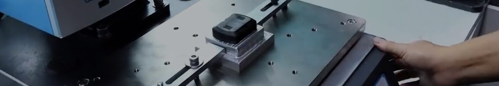


Automotive Light Guide Strip Mold
FEATURES
With over 28 years of injection mold manufacturing and precision molding experience, Ansix Tech has emerged as a trusted global partner for automotive lighting applications. Our expertise spans the full spectrum of the product realization cycle—from initial design verification and prototype development through DFM consultation, mold flow analysis, precision mold fabrication, mass production, and assembly validation. This white paper presents how Ansix Tech translates specialized optical mold manufacturing competencies into tangible client value across five strategic dimensions: equipment infrastructure, mold manufacturing, injection molding process control, full-service lifecycle support, and differentiated competitive advantages.
-
Mold Description
Product Materials:
PMMA
Mold Material:
2344ESR
Number of Cavities:
1*2
Glue Feeding Method:
Hot runner
Cooling Method:
Water cooling
Molding Cycle
42.5s
-
Section One: Hard Power Infrastructure—Building Trust Through Measurable Capabilities
At Ansix Tech, we believe that transparency about manufacturing resources is the foundation of client confidence. Before discussing mold life or dimensional tolerances, we invite our partners to examine the equipment backbone that enables consistent, high-precision optical molding.
Precision Mold Processing Equipment
Optical light guide strips demand mirror-polished parting lines, flawless surface finishes, and sub-micron dimensional fidelity. Our mold machining portfolio is configured specifically for these requirements:
5-Axis High-Speed Machining Centers deliver 0.002mm geometric accuracy on complex freeform surfaces, ensuring that mating lines on transparent components remain seamless and burr-free. This capability eliminates secondary manual polishing costs and prevents light leakage defects that arise from visible parting line misalignment.
-
The mold manufacturing process and product material selection
Slow Wire EDM enables the fabrication of 0.03mm micro-slots and narrow ribs without heat-affected zone distortion or burr formation. For thin-wall light guide features that resist conventional machining, wire EDM preserves wall integrity while achieving positional tolerances that sustain optical uniformity.
CNC EDM & Precision Electrode Grinding Centers provide the fine finishing required for micro-optical surface patterns. When combined with our in-house electrode manufacturing, this eliminates external vendor dependency and accelerates mold repair cycles.
Injection Molding Machine Fleet
Light guide strips range from short interior ambient lighting bars (150 mm) to complex front grille signature strips exceeding 1200 mm. Our machine fleet spans 30 tons to 400 tons, configured with:
All-Servo Electric Drive Systems delivering ±0.1% shot-to-shot repeatability. For light guide production, where melt temperature uniformity directly impacts clarity and stress birefringence, servo-electric precision ensures every mold cycle replicates the same optical performance standard.
Liquid Temperature Control (LTC) Zone Management with integrated mold temperature controllers achieving cavity-to-cavity thermal balance within ±1°C. For thick-wall PC light guides (5mm–15mm typical wall thickness),±2°C temperature stability across core and cavity faces prevents differential shrinkage zones that cause rainbow banding and optical distortion.
Real-Time Process Monitoring with closed-loop feedback that automatically adjusts injection speed and pressure decay profiles based on cavity sensor inputs. For OEMs requiring PPAP documentation, our machine logs provide full parameter traceability.
Quality Assurance & Metrology
Every Ansix Tech mold undergoes full dimensional validation before leaving our facility:
CMM (Coordinate Measuring Machine) inspection delivers complete geometric reports with feature-by-feature comparison against CAD baseline.
Optical 3D Scanners enable non-contact full-surface evaluation for freeform optics, particularly valuable for light guide components with draft angles and varying cross-section profiles.
Critical Dimension Capability (CPK ≥ 1.33) is guaranteed on all customer-identified key characteristics, including sealing interfaces, mounting boss positions, and optical lens surface profiles.
Hardness & Material Certification accompanies every mold shipment, including material heat treatment curves and micrographic grain structure documentation for tool steel validation.
Section Two: Mold Manufacturing Core Competencies—Specifications That Become Guarantees
For automotive light guide strip projects, customers most urgently need clarity on four dimensions: mold lifespan, achievable tolerance, cycle time, and emergency repair responsiveness. Ansix Tech delivers explicit, measurable commitments in each area.
Mold Lifespan: Converting Steel Selection into Production Assurance
A mold is an investment in your production capacity. We tie material selection directly to cycle count guarantees:
Tier Application Example Tool Steel Guaranteed Service Life Customer Value
Premium Optical High-clarity light guide strips, exterior lighting optics S136 (mirror polish grade, Ra ≤0.01μm achievable) 500,000–1,000,000 shots Eliminates unplanned mold changeover downtime across 3–5 years
High-Temperature Surrounding components with glass-filled engineering plastics (PC+GF, PPS+GF) 2344 / 8407 / H13 (high hot hardness) 500,000 shots Prevents thermal cracking and premature failure under 280°C+ melt conditions
General Precision Interior trim light guides, non-optical housings NAK80 / 4Cr13 / 9Cr18 500,000+ shots (≤100,000 for glass-filled applications) Balances capital cost with extended production life
Ultra-High Life High-cavitation family molds, 24/7 high-volume programs DC53 / SKD11 / SKD61 1,000,000+ shots Maximizes asset ROI for multi-year platform programs
S136 steel delivers corrosion resistance that is three times that of NAK80 in halogenated polymer environments, with mirror-polish capability that maintains ≥92% light transmission after 2 million cycles. For mold frame structures, we specify P20-grade steel optimized for structural rigidity rather than surface cosmetics—because cost optimization matters at every design layer.
Achievable Tolerances: Matching Precision to Part Function
Automotive light guide strips have three distinct tolerance zones:
Component Zone Typical Part Feature Achievable Ansix Tolerance Customer Benefit
Critical Optical Surface Light injection surface, light extraction microstructures ±0.005mm (Optical Grade) Eliminates hot-spot artifacts and uneven luminance
Mounting/Assembly Interfaces Clip posts, screw bosses, sealing grooves ±0.01mm–±0.02mm (Precision Grade) Ensures drop-in assembly with mating housing components
Non-critical Architecture Drafted sidewalls, interior ribs ±0.05mm (Commercial Grade) Reduces unnecessary manufacturing cost allocation
For transparent light guide components, we certify critical surface finishes to Ra ≤0.02μm prior to production approval, verifying through white-light interferometry measurement.
Gate and Runner Systems: Preventing Rejects Before They Start
Light guide strips fail most often due to flow marks, optical haze, weld lines, and long-term stress cracking. Ansix Tech applies systematic mold flow analysis for every light guide project, simulating melt front advancement, pressure distribution, air trap locations, and shear heat accumulation during cavity filling.
Based on analysis, we recommend and implement:
Hot Runner Systems for zero-runner waste, eliminating regrind quality concerns on optical-grade resins.
Valve-Gate Sequential Control to manage pressure decay in long, slender cavity geometries, preventing visible knit lines across illuminated zones.
Optimized Gate Placement that positions weld lines in non-critical areas where they will not fall within the visible light path.
Lead Time Commitments
Mold Complexity Standard Lead Time Expedited (Premium Justified) Toolling Quality Validation
Simple Two-Plate Mold 10 days Not applicable (expediting minimal) Basic dimensional validation only
Medium-Complexity (Standard Light Guide Strip) 25–35 days 20 days with parallel processing Normal validation—T0 samples, DFM report
High-Complexity (Multi-cavity, Hot Runner, Thick Wall, Large Format) 45 days 30–35 days (validated prior authorization) Enhanced validation—full FAIR before shipment
In all expedited cases, thermo-mechanical simulation cycles and cooling system validation are performed concurrently with mold machining, never eliminated.
Section Three: Injection Molding Process Control—Turning Process Discipline into Quality Assurance
Customers fear visible cosmetic defects in their light guide shipments: sink marks visible as dark spots, weld lines interrupting uniform illumination, residual stress causing warpage and seal failure, dimensional instability between production batches. Ansix Tech has systematized injection molding process management to eliminate these concerns.
Process Standardization with MES Integration
Every Ansix molding machine connects to a centralized Manufacturing Execution System:
All process parameters (melt temperature profile, holding pressure transition, injection velocity stages, cooling time, mold temperature zones) are locked at qualification and inaccessible to production floor operators.
Parameter adjustments require engineering authorization and trigger a formal change control ticket.
First-article and last-article parts from each lot receive full dimension verification, with SPC charts maintained for all customer-specified critical dimensions.
Dimensional Stability Control
The primary enemy of light guide dimensional accuracy is non-uniform cooling—warpage initiates when one region of the part solidifies faster than another. Ansix Tech deploys:
Zone-Controlled Mold Temperature Management with separate circuits for core and cavity halves, maintaining thermal differential within ±2°C across the molding face.
Conformal Cooling Channel Design following the natural curvature of the part, particularly for J-shaped, S-curved, and perimeter light guide geometries. Compared to straight-drilled cooling, conformal channels reduce hot-spot variance and decrease cycle time by 15–25% while improving dimensional consistency.
In-Mold Pressure/Temperature Sensors providing closed-loop feedback to the injection unit, enabling real-time compensation for environmental changes during long production runs.
For thick-walled PC light guides—where cooling time increases proportionally to the square of wall thickness—we apply these controls rigorously to achieve 0.02mm week-to-week stability on critical mounting features.
Surface Quality & Optical Grade Standards
Surface Quality Level Definition & Use Case Ansix Deliverable
SPI A1 (Mirror Polish) Front-surface optical path, light input face Ra ≤0.008μm, high-clarity transmission
SPI A2 (High Quality) All visible surfaces on illuminated light guide Ra ≤0.02μm, streak-free, weld-line invisible
SPI B1 (Satin/Matte) Concealed surfaces, internal reflector faces Ra ≤0.08μm, diffuse reflection consistent
SPI C1 (Texture) Anti-glare surfaces, scratch-hiding areas Standard texture depth, uniform
For printed or coated light guides (e.g., blackout masking, diffusion coatings), we incorporate compensated shrinkage offsets into mold geometry, achieving ±0.1mm print registration accuracy.
Special Engineering Material Capabilities
Over 28 years, Ansix Tech has molded light guide components from virtually every engineering resin relevant to automotive optics:
Material Category Specific Grades Experience Highlights
Optical PC Covestro Makrolon® LED2245/LED5102, SABIC LEXAN®, Teijin Panlite® PC-1152 High transmission (>90%), low residual stress, UV-stable
PMMA (Acrylic) High-clarity grades for dashboard tell-tale light guides Managing brittleness to prevent cracking during assembly
High-Temp Engineering PPS+40%GF, PEEK, PEI, LCP, PPA Wear-resistant tool steels essential; 300°C+ melt experience
Glass-Filled Structural PC+GF, PA6+GF30, PA66+GF30, PBT Anti-wear inserts, abrasion-resistant coatings on high-flow zones
Liquid Silicone Rubber (LSR) / PFA / PTFE Optical LSR for lens encapsulation, high-clarity fluoropolymer options Specialized screw/barrel configurations required
For UV-exposed automotive exterior light guides, we specify UV-stabilized grades meeting 3,000-hour accelerated weathering performance (SAE J2527 cycles equivalent), ensuring no yellowing or surface degradation across the vehicle service life. For interior lamp applications, UL94 V-0 flame-retardant ratings down to 1.0mm wall thickness are documented.
Section Four: Full-Lifecycle Service—Reducing Your Management Overhead
Many mold manufacturers deliver a tool and walk away. Ansix Tech believes that true partnership extends from initial concept through maintenance support across the production life of the component.
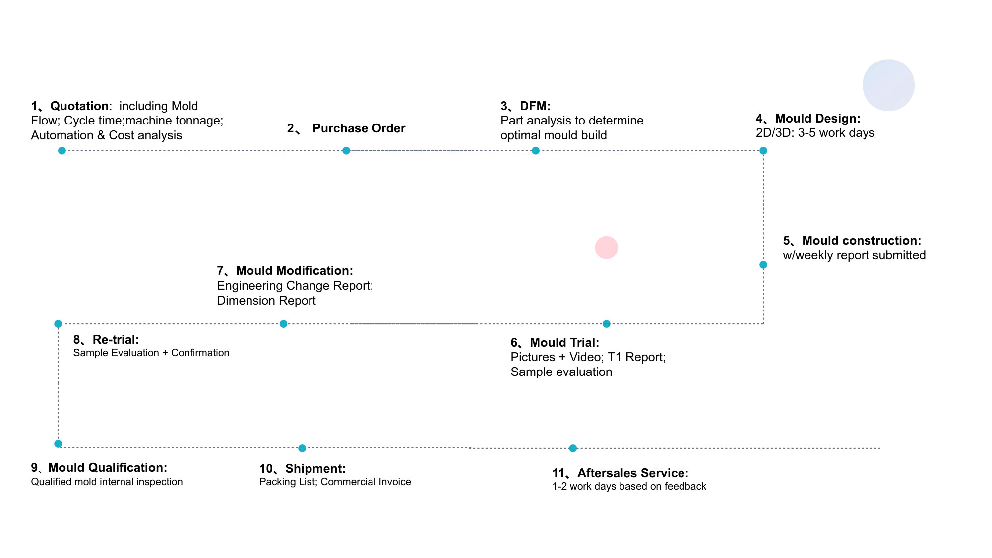
Early DFM Intervention (Pre-Contract Value)
Before any design is locked or any steel cut, Ansix Tech delivers a comprehensive Design for Manufacturability (DFM) Report that includes:
Draft angle recommendations for each surface, ensuring demolding without cosmetic drag marks
Wall thickness optimization to eliminate sink marks while maintaining optical performance
Gate placement recommendations with location restrictions (e.g., “gate must not be on visible surface”)
Ejector pin marking allowances with documented maximum permitted protrusion
Predicted weld line positions with proposed mitigation strategies
This upfront analysis prevents scenarios where a customer spends weeks and thousands of dollars on a mold only to discover that the designed part cannot be molded or assembled.
Prototype & Trial Phases
Ansix Tech delivers incremental validation rather than a single “final answer.” Our staged approach includes:
T0 Samples: First-shot parts demonstrating that the mold fills and ejects
T1-T3 Improvement Samples: Each trial includes a formal Corrective Action Report documenting modifications and the rationale behind each change
Rapid Change Insert System: For design uncertainty zones, we prefabricate interchangeable inserts, enabling side-by-side evaluation of multiple gate or cooling configurations without burning a complete new mold core
Pre-Production Validation Run
Before committing to full-volume production, Ansix Tech executes a 100- to 500-shot validation run, measuring every part and reporting:
Process capability indices (CPK) for each customer-specified critical dimension
First-pass yield rate and defect Pareto analysis
Stabilized cycle time and material consumption per shot
Only when CPK ≥ 1.33 is confirmed does Ansix Tech transition to full-rate production.
Maintenance & Spare Parts Kit
Each mold ships with an EOL-planned spare parts kit including:
Two sets of critical ejector pins
One full set of cavity/core inserts for highest-wear locations
Complete sealing component kit (O-rings, seals for hot runner manifolds)
Machining drawings for reordering
We perform preventive maintenance at 200,000-cycle intervals. Ongoing repairs are invoiced at cost plus service labor—zero mark-up on replacement parts.
Section Five: Differential Advantage—Technical Responses to Common Industry Complaints
Rather than describing our strengths in abstract terms, Ansix Tech addresses the most common frustrations voiced by automotive lighting procurement teams:
Customer Complaint Industry Root Cause Ansix Tech Response & Commitment
“The mold keeps needing repair—it’s disrupting our production schedule.” Surface quality degradation due to insufficient testing prior to delivery. Ansix Standard: Each mold undergoes a 2,000-cycle “burn-in” validation test prior to shipment. We document wear patterns and dimensional drift across the test period. Three-year structural warranty provided (excluding natural wear of moving components).
“We’re spending too much on secondary finishing to remove flash.” Parting line mismatch exceeding 0.02–0.03mm, insufficient mold lock force compensation. Ansix Solution: Parting line machining held to ±0.005mm during manufacture. Auto-locking mold clamp compensation pulls parting surfaces closed under injection pressure. Flash guaranteed ≤0.03mm maximum on any edge.
“We can’t maintain consistent dimensions from week to week.” No real-time feedback between injection molding machine and cavity conditions. Ansix Integrated System: Ultrasound wall-thickness sensors measure as-molded part thickness in-mold. Automatic packing pressure compensation adjusts shot-to-shot. Optional in-mold temperature/pressure sensors provide true closed-loop control.
“Mold repair takes weeks—the injection molding line is dead in the meantime.” No in-house repair capability; mold shop outsources EDM and spark-erosion work. Ansix Rapid Response: In-house electrode manufacturing and EDM/Wire EDM capability. Simple repairs (polishing, minor weld repair, insert replacement) restored within 24 hours. Complex repair turnaround typically ≤72 hours.
“Every design revision triggers a full new mold purchase.” Rigid tool design with no modularity for design iteration. Ansix Smart Design: Interchangeable insert architecture separates high-change zones (gate location, cooling geometry) from fixed mold base. Most common gate relocation issues resolved by swapping a single insert block, not the full mold.
The Ansix Tech Value Equation: Engineering Translation into Client Economics
To our clients, a light guide strip mold is not a block of tool steel—it is a production asset. A well-designed mold runs without technician babysitting, produces minimal flash requiring manual removal, and maintains stable dimensions without constant adjustment. A poorly designed mold becomes a maintenance burden and a quality liability.
Ansix Tech designs each mold with three operational priorities in mind:
Runner-Free Hot Runner Configuration: Eliminates 100% of runner scrap, saving 5–12% material cost directly for every shot produced compared to cold runner alternatives.
Balanced Cooling & Venting Layout: Prevents hot-spot-induced warpage and trapped-gas burning. Operators spend zero time “tweaking” molds between shifts—once qualified, the mold runs repeatably.
Modular Insert Construction: When your product design evolves—including gate location changes or wall thickness adjustments—we replace only the affected insert, not the entire mold. Typical modification cost reduction: 40–60% on design changes.
Material Selection Strategy: Balancing Performance and Cost
Light guide strip optical performance begins and ends with material selection. The two primary optical polymers used in automotive light guide strips—PMMA (acrylic) and PC (polycarbonate)—present fundamentally different processing and performance profiles:
PC (Polycarbonate) for Functional Lighting
Preferred for headlamp light guides, exterior signature lighting, safety-critical illumination.
Advantages: Impact strength (safety-grade toughness), heat deflection temperature up to 130–140°C, UL94 V-0 flame retardancy available down to 1.0mm
Processing Challenges: Requires thorough drying before molding, tight melt residence time control to prevent yellowing, higher viscosity demands temperature-controlled mold surfaces
Ansix-Recognized Grades: Covestro Makrolon® LED2245 (highest transmission/low viscosity), SABIC LEXAN® LUX series (broad flow profile), Teijin Panlite® PC-1152 (light guide grade)
For thick-wall PC light guides (>8mm wall thickness), we specify Makrolon® LED2245 HP RE or comparable low-viscosity optical grades to achieve 300°C melt processing without thermal degradation.
PMMA (Acrylic) for Appearance-Focused Lighting
Preferred for interior ambient light guides, dome lamps, tell-tale indicators.
Advantages: Superior inherent UV stability (no coating required for interior applications), highest light transmission (~92%), excellent surface hardness (scratch-resistant)
Processing Challenges: Brittleness during assembly handling, must avoid sharp corners that initiate stress cracking
Key Consideration: Visible weld lines are more pronounced in PMMA, requiring meticulous gate positioning
Glass-Filled Engineering Resins for Structural Light Guide Components
PPS+40%GF, PBT+GF30, and PEI (Ultem®) serve applications where the light guide also carries structural load. These materials:
Demand high-hardness tool steels (H13, 2344) to resist abrasion over 300,000+ cycles
Require enlarged gates to accommodate poor flow characteristics
Achieve UL94 V-0 flame classification with minimal additives
For each material, Ansix Tech provides a Material Specification Summary Report including:
Recommended melt and mold temperature windows
Shrinkage factors and recommended machining offsets
Safety data sheets (SDS) and regulatory compliance declarations
Proven cycle times from validated tooling
Quality Verification & Testing Protocol
Ansix Tech’s commitment to quality does not end at mold shipment. Our post-delivery certification includes:
Dimensional Verification (Full Reporting)
CMM measurement of all customer-specified critical dimensions
Optical scanning for freeform surface conformance (where requested)
CPK calculation based on 30-piece pre-production run
Optical Performance Validation
Transmission measurement using calibrated light source and photometer
Uniformity scan across the length of the light guide to detect luminance variation >10%
Bubble/void detection through high-magnification visual inspection of light extraction zones
Mechanical & Environmental Standards
IATF 16949 automotive quality management system compliance (certified)
ISO 9001 for general manufacturing quality controls
PPAP Level 3 submission capability for Tier 1 OEM programs
For LED-integrated light guide systems, we support LM-80 testing protocols to validate lumen maintenance and color stability across the component’s service life.
Packaging & Logistics: Delivering Quality Intact
An unprotected optical component arriving with scratches is an reorder. Ansix Tech’s packaging protocol:
Anti-scratch film interlayers between individual components for direct-loading into automated assembly cells
Tray-based packaging designed for your specific part geometry, reversible orientation to prevent surface marking
ESD-safe materials for electronics-adjacent assemblies where light guides interface with LED PCBs
Export-qualified palletization documentation for air and ocean freight
Our logistics team coordinates with global forwarders to provide EXW, FOB, CIF, and DDP terms suited to your regional receiving hub.
Industry Experience: Proven Track Record in Automotive Lighting
Ansix Tech’s credibility in automotive light guide molding is built on completed programs, not hypothetical capabilities:
Mercedes-Benz Front Transparent Light Guide Light Bar: Full mold design, mold flow analysis, and precision manufacturing. Process complexities included large curved surfaces requiring conformal cooling design, strategic gate placement to eliminate flow lines across luminous surfaces, and mold materials specified as 2344H with oil cooling delivering 58.5-second molding cycles.
Heavy-Duty Truck Clearance Lamp Optical Components: Long-form light guides with wall thickness variations managed through multi-stage gate sequencing and press/velocity profiling.
Euro-Spec Taillamp Light Guides: Complex 3D sculpted surfaces with tight spatial constraints—multiple optical cavity architectures validated through iterative mold flow simulation.
Home Appliance Light Guide Strips: PC molding on S136ESR tool steel with water cooling achieving 42.5-second cycle times while maintaining SPI A2 surface quality.
Our mold flow analysis practice systematically simulates filling behavior, cooling maps, thermal stress distribution, and shrinkage behavior—identifying weld lines, air traps, and short-shot zones before the mold enters CNC machining.
Cost Reduction Framework: Lowering Your Total Cost of Ownership
Ansix Tech approaches cost optimization across three pillars:
Material Cost Reduction
Hot Runner Integration eliminates all cold runner scrap, reducing resin consumption by 5–12% on every shot vs. cold runner configurations
Material-Specific Process Windows minimize molded-in stress and reduce downstream annealing/conditioning requirements
Alternative Material Proposals where optical requirements permit lower-cost PC or PMMA alternatives while maintaining performance specifications
Processing Cost Reduction
Conformal Cooling Strategy compresses cycle times by 15–25% compared to conventional straight-line cooling networks, directly reducing cost-per-part in high-volume campaigns
Multi-cavity Optimization for high-demand programs increases throughput per molding machine hour
Free-Molding Surface Finishes eliminate hand-polishing operations on concealed part surfaces
Post-Processing Cost Reduction
Flash-Free Parting Line Machining (±0.005mm) eliminates secondary flash-trimming labor on 100% of parts
Consistent Shrinkage Modeling achieves ±0.02mm dimensional stability, eliminating sorting and rework for out-of-tolerance assemblies
Optimized Ejector Configuration prevents part marking marks that would require additional cosmetic finishing
A typical Ansix Tech client saves 15–25% in total production costs (material + processing + finishing) across the mold lifetime compared to baseline competitor pricing while achieving superior dimensional stability and optical quality.
Conclusion: A Partnership Beyond the Mold
Ansix Tech’s 28-year track record in injection mold manufacturing provides the technical depth required for automotive light guide strip success. But our real value lies in our approach to client relationships: we translate every technical specification into your operational results. We invite you to evaluate our work not by our equipment list or material certifications, but by the reliability and efficiency your light guide tooling delivers on your production floor.
Our manufacturing facilities in China combine world-class machining centers, rigorous quality systems, and experienced molding engineers dedicated to optical applications. Whether your program is a low-volume pre-production validation run or a multi-million shot automotive series production campaign, Ansix Tech provides responsive, transparent, and value-driven partnership.
We are ready to review an existing product against our full DFM methodology—so you can see firsthand how we anticipate and eliminate weld line formation, air entrapment, sink mark risks, and thermal deformation before your first mold is machined.
Ansix Tech – Precision Mold Manufacturing & Injection Molding Solutions for Automotive Lighting Optics
�� Email: info@ansixtech.com
�� Website: www.ansixtech.com
�� ISO 9001 | IATF 16949 Compliant | 28+ Years Experience
Ansix Tech Co Ltd
If you have any plans related to Automotive Light Guide Strip Mold , you can contact us at any time. We will turn your ideas into reality, let you realize your dreams, and obtain large orders from the market. Our contact information is info@ansixtech.com. Or contact our CTO, mail: stephen@ansixtech.com
#www.ansixtech.com #ansixtech.com #Automotive Light Guide Strip Mold #Automotive Light Guide Strip Mold moulds #Automotive Light Guide Strip Mold injection molding companies #Automotive Light Guide Strip Mold Canopy Mold injection mold companies #Ansix #Ansix moulds #Ansix china #Ansix tech china #Ansix tech company #Ansix facotry #Automotive Light Guide Strip Mold injection molding #Automotive Light Guide Strip Mold injection tools #Automotive Light Guide Strip Mold injection moulds #Automotive Light Guide Strip Mold plastic mould #Automotive Light Guide Strip Mold plastic tools #Ansix Tech #Ansix molds #Ansix injection molding #Ansix mold factory #injection molding Automotive Light Guide Strip Mold #Ansix mold factory #Automotive Light Guide Strip Mold china #Automotive Light Guide Strip Mold molds #injection factory #Automotive Light Guide Strip Mold injection molding #Automotive Light Guide Strip Mold injection molding factory #injection molding company #Automotive Light Guide Strip Mold injection mold companies #Automotive Light Guide Strip Mold#Automotive Light Guide Strip Mold mold limited #Ansix mold china #Ansix companies #Ansix company China #Automotive Light Guide Strip Mold facotry #Ansix Tech #Ansix Tech mould #Automotive Light Guide Strip Mold injection moulding #injection moulding company #Ansix Automotive Light Guide Strip Mold parts injection mold companies #medical injection molding companieschina #Automotive Light Guide Strip Mold china factory #Ansix moulding companies #Ansix molding company #Automotive Light Guide Strip Mold injection moulding facotry #Ansix Tech mold #Automotive Light Guide Strip Mold mould #Automotive Light Guide Strip Mold plastic injection molding #ansix plastic mold #Mold manufacturing #Automotive Light Guide Strip Mold parts manufacturing #Automotive Light Guide Strip Mold plastic parts factory #Automotive Light Guide Strip Mold injection parts mold #Automotive Light Guide Strip Mold PRECISION MANUFACTURING #Automotive Light Guide Strip Mold #China mold #Automotive Light Guide Strip Mold injection moulding china #Automotive Light Guide Strip Mold mould china #china precision mold #mold in china #Automotive Light Guide Strip Mold mold china #Precision molds #High-precision molds #Automotive Light Guide Strip Mold #Injection molds #Automotive Light Guide Strip Mold Factory #Automotive Light Guide Strip Mold Company #Super Large Injection Mold Factory #Large Tonnage Injection Molding Factory #Automotive Light Guide Strip Mold Company #Automotive Light Guide Strip Mold Factory #2800T Injection Molding Factory #3000 Ton Injection Molding #4500 Ton Injection Molding Factory #Large Mold Injection Molding #Large Plastic Mold Injection Molding Factory #Large Injection Mold Manufacturer #Plastic Mold Factory #Injection Mold #Plastic Mold