


Automotive Light Guide Strip Optical Lens
FEATURES
Mold Manufacturing Equipment
Equipment Type Technical Specification Customer Value
Five-Axis High-Speed Machining Centers 5-axis simultaneous operation with ±0.002mm positioning accuracy, spindle speeds exceeding 40,000 rpm Produces complex aspherical cavity surfaces without visible tool marks or waviness. Your light guide strip’s parting line arrives smooth and burr-free—no secondary finishing required
High-Precision EDM (Electrical Discharge Machining) Micro-precision down to ≤0.001mm for complex cavity surfaces Enables intricate optical micro-features (prisms, light extraction teeth down to R0.075) that cannot be machined directly, ensuring uniform light distribution without “hot spots”
Slow Wire EDM (Wire-Cut EDM) Finishing accuracy ±0.003mm for core holes and shut-offs Achieves 0.03mm micro-pores and narrow slots while preventing thin-wall deformation—critical for multi-cavity light guide strip tools
Coordinate Measuring Machine (CMM) Stationary CMM with thousandth-millimeter accuracy, tactile and optical sensors Every mold cavity is measured and validated before shipment. We issue full dimensional inspection reports with critical feature CPK ≥ 1.33, eliminating assembly surprises at your facility
Laser Interferometer & Optical Profilometry Real-time surface form measurement, deviation ≤0.004mm Verifies aspherical curvature and optical surface quality to sub-micron levels, ensuring your light guide meets photometric performance targets from the first shot
Injection Molding Machine Fleet
Our all-servo-electric injection molding machines span a clamping force range from 30 tons to 4,000+ tons, covering light guide strips from compact interior ambient lighting bars (5mm thick) to large exterior DRL light pipes exceeding 600mm in length.
-
Mold Description
Product Materials:
PMMA
Mold Material:
S136ESR
Number of Cavities:
4
Glue Feeding Method:
COLD runner
Cooling Method:
Water cooling
Molding Cycle
42.5s
Critical Customer Value: Fully servo-electric drive systems deliver repeatable positioning accuracy of ±0.1%. When you produce 500,000 parts over six months, every single shot mirrors the first—no drift, no surprises, no costly rework campaigns.
In-House Metrology Laboratory
Inspection Capability Application for Light Guide Strips Acceptance Criteria
CMM (Contact & Non-Contact) Critical interface dimensions, mounting features, mating surfaces Key dimension CPK ≥ 1.33
Optical 3D Scanning Full-profile comparison against CAD, warp analysis Profile deviation ≤ 0.05mm
Transmission/Chromaticity Testing Light output consistency, color temperature uniformity ΔE < 0.5 across batch
Stress Birefringence Validation Residual stress visualization for PC/PMMA optics Birefringence ≤ 15nm
Why this matters to you: We don’t guess—we measure. Every mold ships with a full dimensional report. Every production lot is validated against optical performance benchmarks. You receive data, not promises.
-
Part Two: Mold Manufacturing – Core Competencies in Customer Terms
Precision & Tolerance Control
Dimensional Requirement Industry Norm Ansix Capability Your Benefit
Critical mating surfaces ±0.05mm ±0.005mm Drop-in assembly—no shimming, no bench fitting
Light extraction micro-structures (prisms, teeth) ±0.01mm ±0.005mm Consistent light output across the entire strip length, no localized “spots” or “dips”
Optical surface roughness (Ra) <0.02μm (SPI A-2) <0.01μm (SPI A-1 / A-0) Maximum light transmission, minimal scattering—brighter output with fewer LEDs
Customer value translation: Tighter tolerances directly reduce your assembly cost per vehicle. When every light guide strip fits perfectly on the first try, your assembly line runs faster, rework rates drop, and your bottom line improves.
Mold Steel Selection – Matching Material to Mission
We choose mold steel based on your specific production requirements, not a one-size-fits-all formula. Each selection is documented with material certificates and heat treatment curves.
Mold Component Steel Grade Hardness Application Context Customer Value
Mold Base P20 / 1.2311 Pre-hardened 28–32 HRC Structural foundation, non-wear surfaces Reduces initial mold cost without compromising core functional areas
Cavity / Core (Optical Surfaces) S136 / 1.2083 / M340 48–52 HRC after heat treatment For PC and PMMA light guides requiring mirror-grade optical finish. High nitrogen stainless steel delivers exceptional corrosion resistance Surface remains optically perfect over millions of shots. No rust, no pitting, no degradation in light transmission
Cavity / Core (High-Volume GF Materials) H13 / 1.2344 / 8407 / SKD61 48–52 HRC For glass-fiber reinforced plastics (PPS+40%GF, PA6+GF30) where abrasive wear is a concern Tool withstands abrasive glass fibers without premature wear. Your 500,000-shut tool runs like new at 400,000
Wear-Resistant Inserts NAK80 / P21 Pre-hardened ~40 HRC High-cycle precision electronics housings, connector mold areas requiring exceptional wear resistance Pre-hardened delivery cuts lead time by 30%. Achieves 5 million shots with ≤±0.02mm deviation
High-Temperature Inserts 2343 / 2344 / DC53 50–55 HRC For PEEK, PEI, LCP, and other high-heat engineering plastics Maintains dimensional stability at elevated temperatures—no creep, no deformation
Life Expectancy Commitment:
Material Processed Mold Life Guarantee
Unfilled PC / PMMA ≥ 1,000,000 shots
Glass-fiber reinforced materials (up to 40% GF) ≥ 500,000 shots
High-temperature engineering plastics (PEEK, PEI, LCP) ≥ 300,000 shots
Full mold structural warranty included—not limited to consumable wear components.
Mold Type Portfolio – Choosing the Right Architecture
Mold Type Best Application for Light Guide Strips Why It Matters to You
Hot Runner Systems (Valve Gate) Optical-grade PC/PMMA light guides requiring zero gate vestige on visible surfaces Needle valve gate design (0.6–1.0mm gate diameter, ±1°C temperature control) eliminates gate marks, reduces material waste by 15–25%, and improves optical surface quality
Open Hot Runner Non-visible light guide mounting features, high-cavitation tools Lower initial tooling cost for non-optical surfaces; ideal for high-volume commodity applications
Stack Molds (2-plate / 3-plate) High-volume light guide strips with 2x or 3x cavity count within same machine footprint Doubles or triples output per machine cycle. Your production capacity doubles without buying additional injection molding machines
Two-Shot / Multi-Component Molds Bi-color light guides (e.g., red turn signal + white DRL in one unified strip) Eliminates secondary assembly operations. One molding cycle = one finished light guide strip, ready for shipping
High-Gloss / Mirror-Finish Molds All transparent light guides requiring SPI A-1 or A-0 optical finish Mirror-polished cavity surfaces (Ra < 0.01μm) deliver crystal-clear transparency rivaling glass while saving 40–60% in component weight compared to glass optics
Gate and Runner Optimization – Where Science Meets Experience
We don‘t guess where to put the gate. Every project begins with Moldflow simulation to:
Predict weld line locations before steel is cut
Identify gas trap zones that would cause burn marks or voids
Optimize gate count and placement for balanced cavity filling
Validate that all cavities in multi-cavity tools fill simultaneously
Real-world outcome for your light guide strip: No weld lines across the optical path. No burn marks at the end of fill. Every cavity produces identical optical performance. Your scrap rate drops from industry typical 5–8% to below 2%.
Cooling System Design – The Hidden Driver of Cycle Time
Cooling Feature Ansix Standard Customer Value
Conformal Cooling Channels Strategically routed water lines following cavity contours (15–25mm spacing) Cools the part uniformly from all directions. Cycle times reduced by 15–30% compared to conventional straight-drilled cooling
Zoned Temperature Control Independent thermolator zones for cavity vs. core Core/cavity temperature differential maintained ≤ 2°C, eliminating warp due to uneven cooling
Thermal Mapping Validation Infrared thermal imaging during tool prove-out No hot spots. No cold spots. Every batch of light guides comes out straight and flat
Mold Delivery Standards – Predictable Lead Times
Mold Complexity Standard Lead Time Express (Premium)
Simple Prototype / Bridge Tool 10–15 days N/A
Medium Complexity (2–4 cavities, medium optics) 25–35 days 20–25 days
High Complexity (Multi-cavity hot runner + conformal cooling + optical-grade finish) 35–50 days 28–35 days
*Express option maintains all validation steps: DFM review → Moldflow simulation → T0 sample → dimensional inspection → on-site tryout. No shortcuts, just compressed parallel processing.*
2,000-Shot Pre-Delivery Validation
Before your mold leaves our facility:
2,000 consecutive production shots are run on our injection molding machines
Every 500 shots, critical dimensions are recorded and trend-analyzed
Wear report documents part quality stability across all 2,000 cycles
Any drift triggers corrective adjustment before shipment
Customer value: Your mold arrives at your facility ready to run. No debugging. No “first 500 are scrap.” No surprise rework weeks into production. Your production line starts earning revenue on Day 1.
Part Three: Injection Molding Process Control – Eliminating Customer Quality Anxiety
We‘ve spent 28 years learning what keeps our customers awake at night: shrinkage, flash, dimensional instability, and batch-to-batch color variation. Here’s how we eliminate each one.
Process Standardization – Taking the Mystery Out of Molding
Concern Traditional Shop Ansix Solution
Parameter drift over time Operators adjust “by feel” All molding machines networked to MES (Manufacturing Execution System). Every parameter (temperature, pressure, speed, time, hold profile) is locked
Unauthorized changes Anyone with machine access can adjust settings Only approved engineers can modify parameters. Full audit trail records every change—who, what, when, and why
Batch-to-batch variation Each shift runs “a little different” First-article and last-article inspection for every batch. Full dimensional and optical comparison before release
Dimensional Stability – Consistency You Can Bank On
Stability Metric Industry Typical Ansix Capability
Short-term repeatability (same batch) ±0.03mm ±0.01mm
Long-term stability (3 production batches over 7 days) ±0.05mm ≤0.02mm key dimension drift
Warpage control Empirical guess Real-time simulation validated against actual molded parts
What makes this possible:
Ultrasonic wall thickness sensors mounted in mold cavities provide real-time feedback on melt-front advancement. If wall thickness drifts, the control system automatically adjusts packing pressure to compensate—before a single defective part is produced.
In-mold cavity pressure and temperature sensors create a closed-loop control system. When the machine sees a pressure deviation of >2%, it self-corrects without waiting for human intervention.
2°C core/cavity differential cap through zoned mold temperature control ensures uniform cooling. Uneven cooling = warp. No uneven cooling = straight parts.
Customer value: Your assembly automation doesn‘t need to accommodate “wobbly” light guides. Your CPK reports show stability your Tier 1 customers will validate. Your reject rate is predictable and low.
Surface Finish & Optical Quality – The Standard That Matters
Quality Attribute Ansix Capability
Transparent part clarity (PC/PMMA) No bubbles. No flow lines. No silver streaks. SPI A-1 optical finish with Ra ≤ 0.01μm
Replicated micro-structures Prism angles and depths accurate within ±1°. Light extraction uniformity across entire strip length
Gate mark management Valve-gate hot runner systems leave sub-0.2mm witness mark, located in non-optical zones
Flash control Finely matched parting lines (0.005mm fit tolerance) + self-locking clamp force compensation = flash < 0.03mm—eliminate manual deflashing
Special Material Processing Experience
Ansix has successfully injection molded light guide components from the following materials, each with documented process windows established through Design of Experiments (DOE):
Standard Optical Materials:
PC (Polycarbonate) – Optical Grade: Covestro Makrolon® LED/OD, SABIC Lexan® OQ series. Light transmission 88–92%. Excellent impact resistance. Handles LED operating temperatures up to 120°C
PMMA (Polymethyl Methacrylate) – Optical Grade: Highest light transmission (92–94%), excellent UV stability, cost-effective processing. Ideal for interior ambient lighting where impact exposure is low
PC/PMMA Alloys: Blends engineered to balance PC’s toughness with PMMA’s clarity and scratch resistance
High-Performance Engineering Plastics:
PPS + 40% GF: Exceptional chemical and thermal resistance for under-hood light guide applications where ambient temperatures exceed 150°C
PA6 + GF30: High mechanical strength combined with good optical properties for structural light guide assemblies
PEEK / PEI / LCP: Ultra-high temperature resistance (up to 260°C continuous) for lighting components exposed to extreme heat
COC / COP (e.g., TOPAS®, ZEONEX®): Ultra-low birefringence, high purity, moisture-resistant—specified for premium automotive optical systems where optical distortion must be absolutely minimized
Specialty Processing Requirements by Material:
Material Drying Requirements Melt Temperature Mold Temperature Key Concern
Optical PC 120°C × 4h, ≤0.02% moisture 280–320°C 80–140°C Avoid residual stress—requires slow fill and extended hold
Optical PMMA 80°C × 3h, ≤0.02% moisture 220–250°C 50–120°C High viscosity demands careful runner design—poor flow leads to short shots
PPS+40%GF 150°C × 3h 300–340°C 130–150°C Abrasive—requires wear-resistant tool steel (H13 class)
PEEK 150°C × 3h 360–400°C 160–200°C Corrosive at high temperature—spec stainless tool steel required
Customer value: We‘ve already solved the material-specific processing challenges. You don’t pay for our learning curve. You pay only for our proven capability.
Environmental Qualification Support:
UL94 flammability ratings: V-0, V-1, V-2, HB
UV stability: Accelerated weathering testing to 3,000 hours with documented ΔE < 2.0
Thermal cycling: -40°C to +120°C, 500 cycles, no cracking or delamination
Humidity resistance: 85°C / 85% RH, 1,000 hours, no surface degradation
Part Four: Compliance to VDA 6.3 and IATF 16949 – Because Automotive Quality is Non-Negotiable
Ansix Tech is fully compliant with the automotive industry‘s most rigorous quality management standards. This isn’t marketing language—it‘s the foundation of how we operate every day.
IATF 16949:2016 Certified Process Management
Our quality management system is structured around the process approach required by IATF 16949, the global standard for automotive quality. For every light guide strip project, this means:
IATF 16949 Requirement How Ansix Delivers Value to You
Product Design & Development APQP (Advanced Product Quality Planning) documentation from concept through production launch. Your DFM, Moldflow analysis, and FMEA are formally documented and reviewed at every phase gate
Control Plans (Process Flows) Every step—material receiving, drying, molding, inspection, packaging, shipping—has a documented control plan with defined reaction plans for out-of-spec conditions
PFMEA (Process FMEA) Systematic risk assessment for every process step. Potential failure modes (e.g., flash, short shots, dimensional drift) are assigned RPNs and mitigation actions before production begins
PPAP (Production Part Approval Process) Full PPAP Levels 1–4 available. Dimensional reports, material certifications, capability studies (CPK ≥ 1.33 for critical features), appearance approval reports (AAR), and functional test results
Measurement System Analysis (MSA) All inspection equipment is validated through Gage R&R studies (<10% variation). Your measurements are reliable because our measurements are reliable
Statistical Process Control (SPC) Real-time monitoring of critical process parameters with control charts. Out-of-control conditions trigger immediate investigation and corrective action
VDA 6.3 Process Audit Compliance
VDA 6.3 is the German Automotive Industry Association‘s standard for process auditing—widely adopted by German OEMs as their supplier quality benchmark. Ansix maintains systems and documentation ready for VDA 6.3 audit at any time.
What VDA 6.3 compliance means for you:
VDA 6.3 Dimension Your Benefit
Project Management Formalized milestone tracking with clear deliverables. You always know exactly where your project stands
Product Development Structured design reviews, DFM documentation, and prototype validation before production tooling begins
Supplier Management Your material suppliers are pre-qualified with documented performance records. No gambling on raw material quality
Process Analysis (Production) Every injection molding process is analyzed, optimized, and validated before mass production. No process instability means no production surprises
Customer Satisfaction Formalized complaint management and corrective action (8D reporting). If something does go wrong, you get a documented root cause analysis and permanent corrective action—not excuses
Why this matters to you:
When an OEM auditor walks through our facility—and they do, frequently—they don‘t see a generic “quality policy” framed on a wall. They see:
Documented process flows with reaction plans
PFMEAs with RPNs and mitigation actions
Control plans aligned exactly with your part number
CPK data for every critical feature, updated daily
Calibrated inspection equipment with traceable certification
Operator training records proving competency verification
Your supply chain risk is minimized because Ansix operates to standards that OEM quality managers trust. When you present our PPAP package to your customer, the documentation speaks the language they require—no translation, no rejection, no delay.
Part Five: Cost Control – The Ansix Advantage
We don‘t just discuss cost reduction. We engineer it.
Material Cost Optimization
Cost Driver Traditional Method Ansix Approach Savings Realized
Material selection Default to “safe” expensive grade Advanced Moldflow simulation identifies optimal material grade and flow characteristics 10–15% reduction in raw material cost without compromising part performance
Regrind / Recycling 15–25% material waste from sprues and runners Hot runner valve-gate systems eliminate cold runners. Zero waste from sprue removal, zero regrind handling 15–25% material cost savings per part
Gate location optimization Aesthetic priority often sacrifices yield Simulation-driven gate placement balances optical quality with material efficiency 8–12% reduction in project-wide scrap rate
Process Efficiency Gains – More Parts per Hour
Efficiency Metric Industry Baseline Ansix Achievement Annual Impact per Tool
Cycle time 60–90 seconds for typical light guide 45–70 seconds 15–25% higher daily output → lower per-part overhead cost
First-pass yield 85–90% typical for optical parts 96–98% 50–70% reduction in scrap cost → directly to your margin
Changeover time between batches 2–4 hours <45 minutes Faster color changes → more production hours → lower cost per part
Tooling Cost Optimization – Get More Tool for Your Investment
Cost Category How Ansix Reduces Your Investment
Hybrid steel selection High-polish S136 only on optical surfaces. P20 or H13 everywhere else. Same tool life, lower upfront cost
Gas vents and venting channels Strategically placed venting eliminates burn marks without requiring mold disassembly for cleaning between batches—less downtime, lower maintenance cost
Standardized component libraries Interchangeable core/cavity inserts, ejector pins, and leader pins across multiple tools. Your replacement inventory cost drops
DFM-driven design Catching moldability issues at the CAD stage rather than the steel-cutting stage saves weeks of rework. DFM review identifies 8–12 potential design improvements per project before any machining begins
Post-Molding Cost Elimination
Hidden Cost Traditional Approach Ansix Solution Your Savings
Manual flash removal 3–5 seconds per part grinding/sanding flash Precision-matched parting lines produce parts with <0.03mm flash—no manual intervention required
5
,
000
–
5,000–15,000 per year in labor cost per tool
Gate trimming Manual gate snipping adds cost and inconsistency Hot runner valve gates eliminate the gate entirely. Part exits mold fully finished Eliminates gate trimming station → 1–2 fewer operators per shift
Secondary cleaning Degating leaves surface contamination requiring cleaning No gate marks = no cleaning required. Part goes directly from molding machine to packaging Reduced handling, reduced contamination risk, lower labor cost
Quality Cost Reduction – Preventing Rejects Before They Happen
Quality Metric Industry Typical Ansix Achievement
Incoming inspection rejects 2–5% of shipments <0.5%
Customer returns 1–3% of annual volume <0.3%
Sort-and-rework costs
10
,
000
–
10,000–50,000 per incident Nearly eliminated through first-run-correct capability
Total impact: Every dollar you spend with Ansix goes further because fewer dollars are wasted on rejects, rework, returns, and customer chargebacks.
Long-Term Maintenance Cost Reduction
Maintenance Item Typical Industry Ansix Commitment Value to You
Spare parts kit Customer must stock and manage Complete set of spare ejector pins, core inserts, and wear plates included with mold delivery No emergency freight costs. No production stoppages waiting for parts from overseas
Scheduled maintenance Customer manages with third-party shops Ansix offers scheduled tool maintenance at 200,000-shot intervals. We pick up, inspect, clean, and return your mold 35% lower maintenance cost compared to local third-party shops. OEM-quality work guaranteed
Emergency repairs 2–4 weeks typical turnaround for overseas molds In-house electrode manufacturing and EDM means most repairs complete within 24 hours. Mold never leaves our control Dramatically shorter downtime during emergencies. Your production line gets back online faster
What this looks like in dollars:
For a typical automotive light guide strip running 500,000 parts annually:
Cost Category Without Ansix Optimization With Ansix Solution Annual Savings
Raw material $120,000 $102,000 $18,000
Scrap (rejects + rework) $45,000 $12,000 $33,000
Manual finishing labor $30,000 $3,000 $27,000
Tool maintenance $12,000 $8,000 $4,000
Incoming quality inspection $8,000 $2,000 $6,000
Total $215,000 $127,000 $88,000
$88,000 in annual savings per program—directly to your bottom line.
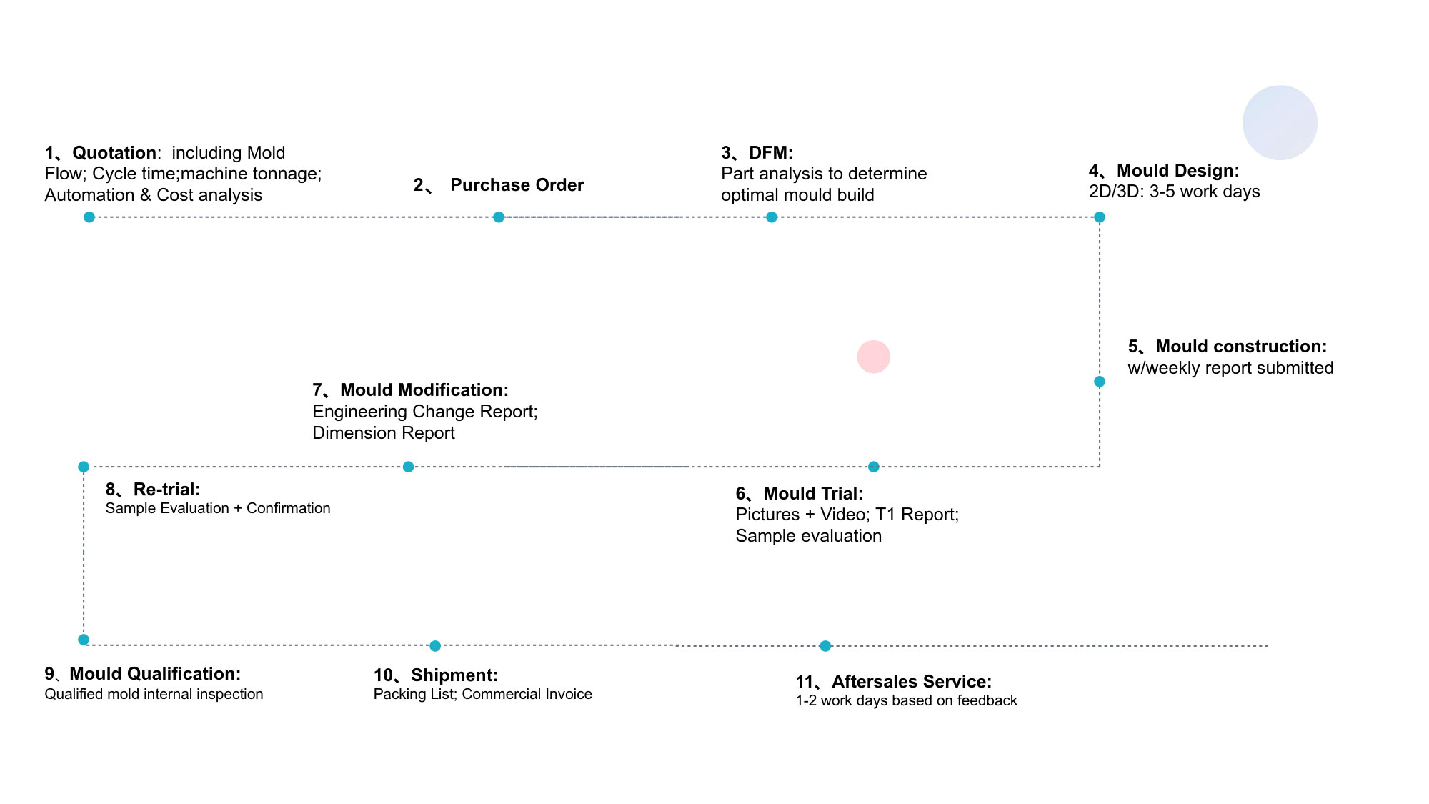
Part Six: The Ansix Full-Service Journey – From Concept to Delivery
Phase 1: Early Engineering Engagement (DFM)
What we deliver before you commit to tooling:
Comprehensive Design for Manufacturability (DFM) report
Mold flow analysis with weld line, gas trap, and fill balance visualizations
Recommended gate locations with justification
Draft angle recommendations (typically 0.5°–1.5° depending on surface finish requirement)
Wall thickness optimization suggestions to reduce sink marks and warpage
Ejector pin location map with placement zones approved for your aesthetic requirements
Critical tolerance identification (which dimensions truly matter vs. where you can relax and save cost)
Customer value: We catch design issues before your tool is cut—when changes cost nothing except CAD time. One DFM review typically identifies 8–12 preventable issues that would have caused
15
,
000
–
15,000–40,000 in tool rework if caught after machining.
Phase 2: Tooling Design & Manufacturing
What happens during this phase:
Final steel selection based on production volume and material type
Detailed mold design with 3D models (SolidWorks/UG) for your approval before machining
Five-axis pre-machining + EMD finishing of optical surfaces
Mirror polishing of all cavity surfaces (SPI A-1 minimum for any surface contacting the optical path)
Assembly and valve-gate/runner installation
Cooling circuit pressure testing and thermal mapping validation
Phase 3: T0–T3 Sampling and Validation
Sample Stage Deliverables Customer Involvement Decision Gate
T0 (First shots) First molded samples from new tool Visual inspection, initial dimension checks Tool runs; no major functional defects
T1 (Adjustment samples) Samples with initial process parameter tuning. Dimensional report. Moldflow analysis vs. actual fill comparison Dimensional sign-off. Visual appearance approval Dimensions within specification; process window defined
T2 (Process optimization) Optimized samples with stabilized cycle time. CPK data for critical features CPK review. Assembly test with your mating components CPK ≥ 1.33 for critical dimensions
T3 (Pre-production validation) 100–500 pilot run parts under production conditions. Full dimension and optical testing Final approval before mass production PPAP submission ready for customer sign-off
Customer value: You see samples at every stage. You have the power to approve or request changes. You are not surprised at launch.
Phase 4: Pilot Production Verification
Before we release the tool for full mass production:
100–500 parts are run on production injection molding equipment
Full dimensional inspection performed on 30 samples from mid-run
Cpk data calculated for all critical dimensions (key feature minimum Cpk 1.33)
Optical performance testing: light output uniformity, color temperature stability across strip length
Visual inspection under magnification for surface defects
Functional assembly test with customer-provided mating components (if available)
Customer value: We validate that the tool runs consistently at production speeds before you approve the PPAP. Your mass production launch is a formality, not an experiment.
Phase 5: Production & Delivery
Service Component Ansix Capability Your Benefit
Production capacity 30–4,000+ ton machines; up to 1 million+ shots per month per tool We scale with your demand. Growth doesn‘t require finding a new supplier
Custom packaging Tray packing, anti-static bags, bulk cartons, custom-labeled boxes to your specification Parts arrive ready to feed into your automated assembly line—no repacking, no contamination clean-up
Logistics Multiple international shipping partners; EXW, FOB, CIF, DDP incoterms available Predictable freight, predictable customs, predictable delivery dates
Lead time—Prototype CNC-machined light guide sample: 5–7 days Engineering concepts validated quickly without committing to production tooling
Lead time—Bridge tool 15–25 days for pilot production before hard tooling completion Product launches stay on schedule while hard tooling is still in progress
Lead time—Production tool 25–50 days depending on complexity Predictable capital investment timeline
Phase 6: Post-Delivery Support
Every Ansix mold ships with:
Complete dimensional inspection report
Material certifications for all steel grades and mold components
Recommended process parameters sheet (temperatures, pressures, speeds, hold profiles)
Spare parts kit (ejector pins, core inserts, seal rings, heater bands)
Mold maintenance guide with lubrication schedule and cleaning intervals
CAD model for reference
Ongoing support:
200,000-shot maintenance inspection and cleaning
24-hour emergency response for critical service needs
Perpetual spare parts availability—even for molds we built 10 years ago
Lifetime mold repair at cost (you pay only for material and labor; we add no markup)
Part Seven: Turnkey Assembly Solutions – More Than Just Molded Parts
Ansix doesn‘t stop at injection molding. We offer complete assembly integration for light guide systems, reducing your supply chain complexity and vendor management overhead.
Assembly Capabilities
Assembly Service Equipment Typical Processes Supported
LED module insertion Precision press-fitting fixtures Insertion of PCB-mounted LEDs into light guide mounting bosses
Ultrasonic welding Ultrasonic welders with custom tooling Joining light guide strip to mounting bracket or housing
Hot staking / Heat staking Heat staking presses with thermocouple control Forming plastic bosses to retain PCBs or lenses without separate fasteners
Solvent bonding Precision dispensing systems Bonding multiple light guide segments into continuous strips (e.g., tail lamp light bars)
Pressure-sensitive adhesive (PSA) application Automated PSA tape applicators Backside adhesive application for direct-to-body interior ambient lighting strips
Optical inspection Vision systems with light output measurement Validating LED alignment and light distribution uniformity before shipping
Value of a Single-Source Solution
Challenge with Separate Suppliers Ansix Single-Source Solution
Mold maker and molder point fingers at each other when quality issues arise One responsible party from start to finish. No finger-pointing—just solutions
LEDs inserted somewhere else can damage molded light guide features LED insertion integrated into the same facility. Assembly quality proactively verified
Multiple vendors = multiple quality systems, multiple purchase orders, multiple invoices One vendor. One quality system. One invoice. Your procurement costs drop
Assembly defects require shipping parts back to molder for rework Defective parts stay at Ansix. Rework happens where molding occurred—not shipped across the country
Customer value: You manage one vendor. One relationship. One quality standard. One delivery schedule. Everything else—molding, assembly, inspection, packaging, shipping—is our job to coordinate. Your team focuses on vehicle assembly, not chasing components from five different suppliers.
Part Eight: Industry Experience – 28 Years of Proven Reliability
Ansix Tech has been designing and manufacturing optical molds and injection-molded components for the automotive industry since 1998—spanning the evolution from halogen to LED to micro-LED lighting architectures.
Documented Success Metrics
Metric Ansix Performance
Years in continuous operation 28+
Automotive light guide molds delivered 2,000+
Molds currently in active production across customer plants 600+
Total molded light guide parts shipped >500 million
Average mold life achieved (PC/PMMA applications) 1.2 million shots
Maximum mold life recorded (single tool) 3.5 million shots and counting
Customer on-time delivery rate (past 36 months) 99.2%
PPM defect rate (global average across all programs) <800 PPM
What Our Customers Say
“Ansix has supplied light guide molds for four consecutive vehicle platforms. Their DFM process consistently identifies manufacturability issues we missed in design. The tools arrive on time and run for years without major intervention.” — Senior Purchasing Manager, European Tier 1 Lighting Supplier
*“We migrated light guide production to Ansix from a competitor after persistent quality issues. Within six months of the transition, our assembly line reject rate for light guide-related defects dropped by 70%.”* — Production Manager, North American Automotive OEM
“The Ansix team supported us through an unplanned production ramp when our primary supplier failed. They delivered additional tools in half the quoted lead time and maintained 100% quality throughout the surge.” — Supply Chain Director, Asian Automotive Module Manufacturer
Part Nine: The Ansix Promise – Turning Engineering into Value
At Ansix, we believe a mold is not a block of steel. It is a revenue-generating asset. A tool designed to produce profit for your business, day after day, million after million.
Every Ansix mold is engineered with attention to:
Robustness — steel selection, cooling geometry, and valve-gate systems optimized for million-shot reliability
Efficiency — shortest possible cycle times at consistent quality, maximizing your ROI per machine hour
Serviceability — accessible components, documented maintenance procedures, and spare parts that are actually available
Every Ansix molding process is designed to deliver:
Low scrap — process windows validated before production starts
No surprises — every parameter locked in MES, every inspection documented
Peace of mind — OEM-grade quality systems supporting every part we ship
Next Step: Put Our Process to the Test
We don’t ask for your trust—we earn it. Before you commit to production tooling, Ansix will perform a full DFM analysis on one of your existing light guide strip designs or CAD files—at no cost.
What a Free DFM Review Includes:
Mold flow analysis showing fill pattern, weld line locations, gas trap zones, and pressure distribution
Draft angle assessment identifying potential ejection issues
Gate placement recommendation comparing 2–3 options with detailed pros and cons
Wall thickness analysis identifying areas where non-uniform thickness may cause sink marks or warp
Material selection advice with grade-specific process parameters and cost-benefit analysis
Cost estimate for tooling based on your annual volume projection
This isn‘t a sales pitch disguised as engineering. This is a working demonstration of how we approach every project—data-driven, collaborative, and relentlessly focused on your success.
You will see, before we cut a single millimeter of steel, exactly how Ansix would solve the manufacturability challenges in your current design. You will see weld lines visualized before they exist. You will see gate location trade-offs quantified. You will see, in hard numbers, the cost impact of alternative design choices.
If our approach aligns with your expectations—excellent. We begin tooling.
If not—you keep the DFM report. The analysis is yours. No obligation. No hard feelings.
Ready to get started?
Contact Ansix Tech for a DFM consultation on your automotive light guide strip optical lens project. Provide your 3D CAD file and target annual volume. We will return a comprehensive DFM and Moldflow analysis within five business days.
Ansix Tech – Precision Molding, Delivered.
Document prepared for: Automotive Lighting OEMs, Tier 1 Lighting Suppliers, and Automotive Module Manufacturers
Authority: Ansix Tech Engineering & Sales Team
Ansix Tech Co Ltd
If you have any plans related to Automotive Light Guide Strip Optical Lens , you can contact us at any time. We will turn your ideas into reality, let you realize your dreams, and obtain large orders from the market. Our contact information is info@ansixtech.com. Or contact our CTO, mail: stephen@ansixtech.com
#www.ansixtech.com #ansixtech.com #Automotive Light Guide Strip Optical Lens #Automotive Light Guide Strip Optical Lens moulds #Automotive Light Guide Strip Optical Lens injection molding companies #Automotive Light Guide Strip Optical Lens Canopy Mold injection mold companies #Ansix #Ansix moulds #Ansix china #Ansix tech china #Ansix tech company #Ansix facotry #Automotive Light Guide Strip Optical Lens injection molding #Automotive Light Guide Strip Optical Lens injection tools #Automotive Light Guide Strip Optical Lens injection moulds #Automotive Light Guide Strip Optical Lens plastic mould #Automotive Light Guide Strip Optical Lens plastic tools #Ansix Tech #Ansix molds #Ansix injection molding #Ansix mold factory #injection molding Automotive Light Guide Strip Optical Lens #Ansix mold factory #Automotive Light Guide Strip Optical Lens china #Automotive Light Guide Strip Optical Lens molds #injection factory #Automotive Light Guide Strip Optical Lens injection molding #Automotive Light Guide Strip Optical Lens injection molding factory #injection molding company #Automotive Light Guide Strip Optical Lens injection mold companies #Automotive Light Guide Strip Optical Lens#Automotive Light Guide Strip Optical Lens mold limited #Ansix mold china #Ansix companies #Ansix company China #Automotive Light Guide Strip Optical Lens facotry #Ansix Tech #Ansix Tech mould #Automotive Light Guide Strip Optical Lens injection moulding #injection moulding company #Ansix Automotive Light Guide Strip Optical Lens parts injection mold companies #medical injection molding companieschina #Automotive Light Guide Strip Optical Lens china factory #Ansix moulding companies #Ansix molding company #Automotive Light Guide Strip Optical Lens injection moulding facotry #Ansix Tech mold #Automotive Light Guide Strip Optical Lens mould #Automotive Light Guide Strip Optical Lens plastic injection molding #ansix plastic mold #Mold manufacturing #Automotive Light Guide Strip Optical Lens parts manufacturing #Automotive Light Guide Strip Optical Lens plastic parts factory #Automotive Light Guide Strip Optical Lens injection parts mold #Automotive Light Guide Strip Optical Lens PRECISION MANUFACTURING #Automotive Light Guide Strip Optical Lens #China mold #Automotive Light Guide Strip Optical Lens injection moulding china #Automotive Light Guide Strip Optical Lens mould china #china precision mold #mold in china #Automotive Light Guide Strip Optical Lens mold china #Precision molds #High-precision molds #Automotive Light Guide Strip Optical Lens #Injection molds #Automotive Light Guide Strip Optical Lens Factory #Automotive Light Guide Strip Optical Lens Company #Super Large Injection Mold Factory #Large Tonnage Injection Molding Factory #Automotive Light Guide Strip Optical Lens Company #Automotive Light Guide Strip Optical Lens Factory #2800T Injection Molding Factory #3000 Ton Injection Molding #4500 Ton Injection Molding Factory #Large Mold Injection Molding #Large Plastic Mold Injection Molding Factory #Large Injection Mold Manufacturer #Plastic Mold Factory #Injection Mold #Plastic Mold