



Molding of PPA Material for Surgical Stapler Pushers
FEATURES
Foundation of Technical Capabilities (Building Client Trust)
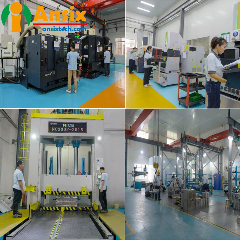
At Ansix Tech, we believe that world-class outputs require world-class inputs. Our manufacturing infrastructure is purpose-built to handle the demanding requirements of PPA material processing for precision medical components.
Mold Manufacturing Equipment
Equipment Type Technical Specification Customer-Value Translation
5-Axis High-Speed Machining Centers 0.002mm precision for complex curved surfaces Your surgical stapler pusher will have a seamless, burr-free parting line that requires zero post-processing. No sharp edges to damage assembly tooling.
Slow Wire EDM (Electrical Discharge Machining) Capable of machining fine micro-holes and narrow slots down to 0.03mm Enables ultra-thin wall sections in pusher geometry without risk of deformation during ejection. Critical for maintaining consistent pusher deflection characteristics.
Ultra-Precision CNC Grinding ±0.001mm surface flatness control Ensures perfect mold plate parallelism, eliminating flash formation at the parting line.
Our mold processing capabilities enable us to achieve tolerances that directly impact your assembly yield and product reliability.
Injection Molding Machine Fleet
Ansix Tech operates a comprehensive range of all-electric servo-driven injection molding machines spanning 30 tons to 400 tons. Each machine features:
All-servo electric drive systems: Repeatable precision of ±0.1% for every single shot. PPA materials require extreme consistency—melt temperature fluctuations as little as 5°C can alter viscosity by over 20%, directly affecting fill pattern and dimensional stability. Our servo-driven machines eliminate hydraulic variability.
-
Mold Description
Product Materials:
PPA
Mold Material:
S136ESR
Number of Cavities:
1*8
Glue Feeding Method:
COLD runner
Cooling Method:
Water cooling
Molding Cycle
12.5s

- The mold manufacturing process and product material selection
All-servo electric drive systems: Repeatable precision of ±0.1% for every single shot. PPA materials require extreme consistency—melt temperature fluctuations as little as 5°C can alter viscosity by over 20%, directly affecting fill pattern and dimensional stability. Our servo-driven machines eliminate hydraulic variability.
Real-time process monitoring: Each machine is integrated with sensors that track injection pressure, melt temperature, screw position, and mold cavity pressure. Parameters are uploaded to our central MES (Manufacturing Execution System) every 0.1 seconds.
Clamping force range: 30–400 tons, covering pusher components from single-cavity prototypes to 16-cavity production tools.
Client benefit: When we say ±0.015mm dimensional consistency across a 100,000-piece production run, we have the equipment data to prove it.
Inspection and Quality Assurance Equipment
Equipment Capability Quality Assurance Value
Coordinate Measuring Machine (CMM) ±0.0005mm resolution Every mold cavity is certified with a full dimensional inspection report before shipment.
Optical Vision Measurement System 0.001mm resolution non-contact measurement Rapid first-article inspection for thin-walled pusher features that cannot tolerate probe contact.
2.5D Image Measurement System ±0.0008mm accuracy Enables 100% inspection of critical dimensions on statistically sampled production lots.
Hardness Tester & Surface Roughness Tester HRC scale, Ra measurement down to 0.01μm Validates heat treatment quality and surface finish. PPA with glass fiber reinforcement will accelerate wear on improperly hardened molds—we verify every critical surface.
Key commitment for surgical stapler pushers: Each mold undergoes full-dimensional validation before delivery. Critical dimensions achieve Cpk ≥ 1.33 (minimum 4-sigma process capability). We provide the statistical proof, not just a verbal promise.
-
Core Competencies in Mold Manufacturing
Mold Life Expectancy — Quantifiable Commitment
Mold Component Material Selection Expected Life (Strokes) Client-Value Translation
Mold Base P20 (pre-hardened) 500,000+ Your mold will outlast your first production contract. No unexpected tooling replacement costs mid-program.
Mold Core/Cavity S136, 2344, 2343, 8407, SKD11/61, DC53, M340, 4Cr13, 9Cr18, NAK80, H13 500,000 guaranteed under GF-reinforced PPA; 1,000,000+ for non-abrasive grades PPA with 30–50% glass fiber is highly abrasive—ordinary tool steel fails within 150,000 cycles. Our hardened stainless steel (S136, M340) resists glass fiber scoring, maintaining cavity finish and dimensional accuracy through high-volume production.
We provide material certificates and heat treatment curves with every mold delivery. Third-party metallurgical analysis is available upon request.
Achievable Tolerances
Component Type Standard Tolerance Precision Grade Medical-Grade Capability
General structural components ±0.05mm Standard production Reliable for non-critical features
Precision gears / Medical components ±0.005mm High-precision Surgical stapler pusher grooves, latch features, and interference-fit surfaces
Client value: A pusher with inconsistent dimensions will cause misfeeding, jamming, or failure to fire. Our ±0.005mm capability ensures every pusher interfaces perfectly with the staple cartridge and driver blade.
Comprehensive Mold Type Capabilities
Our PPA molding expertise encompasses multiple mold architectures:
Mold Type Technical Application Surgical Stapler Pusher Fit
Hot Runner Systems Reduced material waste, shorter cycles, no runner trim PPA material cost savings of 15–25%—rework savings cover the hot runner investment within 3–6 months of production.
Stack Molds Doubles output per machine cycle without increasing clamp tonnage Ideal for high-volume pusher programs. Two-layered cavities produce 2x output from same machine footprint.
Two-Shot / Multi-Material Molds Sequential injection of different materials For pushers requiring overmolded soft-touch surfaces or integrated seals.
High-Gloss Molds Ra < 0.05μm surface finish Critical for transparent or cosmetic components; reduces frictional resistance in the stapler channel.
Gating Strategy Expertise
Gate Type Applicable Geometry Client Value
Submarine (Tunnel) Gate Side-gated components requiring automatic degating Eliminates secondary gate-trimming operations. Reduces labor cost and eliminates risk of operator-induced trim damage.
Pinpoint Gate Balanced filling for multi-cavity tools Ensures identical pusher dimensions from every cavity. No cavity-to-cavity variability.
Edge Gate Larger components with thick sections Simpler mold construction with lower initial cost for lower-volume programs.
Film / Fan Gate Wide, thin-walled sections Reduces flow-induced molecular orientation, minimizing anisotropic shrinkage and warpage.
Critical insight for PPA materials: PPA has relatively high melt viscosity compared to commodity thermoplastics. Poor gate design traps air and creates weld lines, which become failure initiation sites under the cyclic loading of stapler actuation. Our mold flow analysis identifies optimal gate quantity and position—specifically ensuring that any unavoidable weld lines are relocated to low-stress, non-functional areas of the pusher.
Lead Time Standards
Mold Complexity Standard Lead Time Expedited Lead Time Condition
Simple (single-cavity, less than 10 components) 10 days 7 days Full dimensional validation still performed; accelerated heat treatment only.
Medium (multi-cavity, 10–50 components) 25–45 days 20 days Requires advance material order confirmation.
Complex (high-cavitation, hot runner, precision shutoffs) 6–8 weeks Not recommended Quality validation cannot be rushed for critical medical applications.
Client commitment: Expedited delivery does not bypass any quality validation step. Every mold, regardless of timeline, receives full CMM inspection, trial molding validation, and CPK documentation.
Section Three: Process Control in Injection Molding (Reducing Quality Anxiety)
Process Standardization — The MES Lock
All Ansix Tech injection molding machines are connected to our MES platform, which locks all process parameters (temperature, pressure, speed, cooling time) at engineering-approved setpoints. Parameter changes require engineering authorization and are logged with timestamps and operator identification.
What this means for you:
No unauthorized process adjustments during night shifts or weekend production.
Complete traceability: every production batch is linked to the exact machine, mold, material batch, and param set.
First-article and last-article verification before and after every production run.
Dimensional Stability Control
Control Element Technical Specification Quality Assurance Value
Mold Temperature Zoning Mold temperature controllers with <2°C differential between core and cavity Minimizes thermal gradient-induced warpage. Critical for long, narrow pusher geometries that naturally want to bow.
Conformal Cooling Channels 3D-printed or machined cooling lines following pusher contour Reduces cooling time by 30–40% while maintaining uniform cooling. Eliminates hot spots that cause local shrinkage variation.
Ultrasonic Wall Thickness Monitoring Real-time sensor feedback on cavity wall thickness fluctuations Automated compensation of holding pressure to maintain consistent packing.
In-Mold Temperature & Pressure Sensors Closed-loop control of cavity conditions Real-time adjustment of process parameters to compensate for material viscosity variation between batches.
Performance data for similar PPA pusher components: Continuous production across three separate runs over seven consecutive days showed key hole-spacing dimensional fluctuation ≤ 0.02mm. We can replicate this for your pusher geometry.
Surface Finish and Appearance Classification
Appearance Grade Standard Medical Device Applicability
Standard commercial Visual inspection only Non-critical surfaces
SPI A-1 (Diamond Grade) Ra ≤ 0.025μm, flawless mirror finish Optical surfaces, low-friction channels
SPI B-1 (High-Grade Paper) Ra ≤ 0.05μm, fine paper finish Standard medical component surfaces
SPI C-1 (Stone Finish) Ra ≤ 0.20μm Texture for grip or mating surfaces
Value proposition: For surgical stapler pushers, the surface contacting the staple driver must be smooth enough to prevent friction-induced sticking but may require texture on grip features. We specify surface finish on the drawing, validate with a surface roughness tester on every first article, and monitor with periodic sampling throughout production.
Special Materials Processing Expertise
Ansix Tech has validated processing parameters for over 30 engineering thermoplastics, including:
Material Family Specific Grades Experience Key Processing Considerations
PPA (Medical Grade) Amodel® AS-4133 (33% GF), ForTii® Care (30% GF) Melting point >300°C / 572°F; pre-drying critical (<0.1% moisture); mold temp 90–130°C; high injection pressure required (700–1500 kgf/cm²)
PC / ABS Blends Medical-grade alloys Moderate flow; UL94 V-0 flame rating achievable; UV resistance validated to 3000 hours
PEEK Medical implant-grade Extremely high melt temp (>350°C); narrow processing window; exceptional chemical resistance
PPS + 40% GF High-heat structural Good dimensional stability; requires wear-resistant tooling due to glass fiber
LSR (Liquid Silicone Rubber) Medical-grade Two-part injection; cleanroom production; no mold release agents allowed
PPA is our specialty. Medical-grade PPA grades from suppliers including Syensqo’s Amodel® and Envalior’s ForTii® Care offer unmatched thermal performance, with melting points exceeding 300°C and retention of mechanical strength at temperatures up to 280°C. This makes PPA ideal for surgical stapler pushers that may be assembled via surface-mount technology or exposed to steam sterilization cycles.
Section Four: Full-Process Service (Reducing Client Management Costs)
Many mold shops excel at making molds. Few understand that clients do not want molds—they want reliably molded parts delivered on time, at cost, with zero quality surprises. Ansix Tech’s full-process service model bridges this gap.
Early Engagement — DFM (Design for Manufacturability) Report
Before any metal is cut, we provide a comprehensive DFM report that includes:
DFM Element Analysis Delivered Why This Matters to You
Draft angle recommendations Optimal ejection angles for PPA material properties Insufficient draft causes pusher deformation during ejection; too much draft adds unnecessary material.
Wall thickness optimization Uniformity analysis; rib/base ratio recommendations Variable wall thickness causes differential cooling and sink marks that alter pusher compliance characteristics.
Gate location strategy Recommended gate type, location, and quantity based on mold flow analysis Establishes directional fill pattern that affects glass fiber orientation and mechanical strength.
Ejector pin mark locations Mark type, location, and allowable depth tolerance Ejector marks on functional surfaces can create stress risers or interfere with sliding interfaces.
Weld line and air trap prediction Visual map of defect locations from mold flow simulation We identify and mitigate weld lines before mold manufacture—not during trial runs.
Material shrinkage compensation Predicted shrinkage values (typically 0.4% flow direction, 1.2% transverse for 30% GF PPA) Our drawing models incorporate compensated geometry so your part matches the print after molding, not requiring iterative rework.
Client benefit: You receive a detailed report before signing the mold contract—at no charge—identifying all potential manufacturability issues and recommended solutions. One client using our DFM process avoided a $150,000 mold redesign when we identified an un-moldable undercut in their initial design.
Trial Molding and Sampling — T0 through T3
Trial Stage Deliverable Client Action
T0 (First shot) Initial parts for dimensional verification Visual and dimensional inspection; functional test of critical features.
T1 (First optimized) Revised parts with addressed T0 issues Full dimensional certification; begin functional qualification.
T2 (Fine-tuned) Process-optimized parts at target cycle time End-of-line functional testing; begin regulatory compliance documentation.
T3 (Production ready) Validated parts at full production parameters Approve for mass production; tool transfer if required.
At each trial stage, we provide a comprehensive improvement report documenting revisions made and verification results. For complex geometries, we maintain flexibility by designing rapid-change inserts—enabling us to validate multiple design variations without building an entirely new mold.
Low-Volume Validation
Before committing to full-scale production, we offer a 100 to 500-shot pilot run. This trial production encompasses:
Full statistical process control (SPC) monitoring across the pilot run
Cpk calculation for all critical dimensions
Defect Pareto analysis by mold cavity
Process capability certification
Client value: You do not approve mass production until we jointly determine that the process is stable and yields meet your quality targets. We share the risk of process validation with you.
Maintenance and Spare Parts
Service Specification Client Value
Standard spare parts kit Ejector pins, core pins, all wear components Delivered with mold at shipment. Production can continue during routine maintenance without custom ordering long-lead replacement parts.
Scheduled maintenance Recommended every 200,000 cycles; we perform with your approval Extends mold life; prevents unplanned downtime. We track cycle counts and proactively contact you before scheduled service is due.
Lifetime repair Repairs performed at cost (materials + labor only, no profit markup) No unexpected capital reinvestment for normal wear. You pay only for incremental work, not a new mold premium.
We also provide optional on-site repair capability through our in-house electrode manufacturing and EDM facility. Most mold repairs can be completed within 24 hours of receiving the mold.
Section Five: Differentiated Commitments (Direct Solutions to Common Industry Pain Points)
Rather than comparing ourselves to competitors verbally, we address the issues that most frequently frustrate medical device manufacturers working with injection molders.
Common Client Complaint Ansix Tech’s Demonstrated Response
“Our molds require constant repairs, interrupting production schedules.” Every mold we build undergoes a 2,000-cycle run-in test before shipment, accompanied by a detailed wear report. We provide a three-year mold structure warranty (excluding normal wear on consumable components). If a structural issue arises within three years, we repair at no charge.
“Excessive flash means expensive deflashing labor and scrapped parts.” Our parting lines are machined to 0.005mm fit tolerance. We incorporate self-locking toggle mechanisms on machines to compensate for thermal expansion. Batch-to-batch flash is maintained ≤0.03mm—small enough that no manual deflashing is required. You eliminate a post-processing step entirely.
“Dimensional consistency varies between production batches.” Our machines are equipped with ultrasonic wall thickness sensors that provide real-time feedback on packing effectiveness, automatically compensating holding pressure to maintain consistent dimensions. Optional in-mold temperature and pressure sensors enable closed-loop process control that accounts for batch-to-batch material variation. We provide CPK charts with every batch shipment.
“Mold repair lead times are unacceptable—we lose weeks of production.” Ansix Tech operates an in-house electrode manufacturing workshop and EDM department. Most mold repairs (including weld repair and insert replacement) can be completed within 24 hours of receiving the mold. We do not outsource repairs to third-party shops with their own lead time backlog.
“We can’t trust that our molds will hold up for the contract life.” Your mold steel is not an afterthought. For PPA with glass fiber reinforcement, we select hardened stainless steel (S136, M340) or equivalent heat-treated tool steel (8407, SKD-61, DC53) based on expected cycle count. We provide hardness test reports, heat treatment curves, and material certificates with delivery. No compromises.
“We suspect regrind material mixed into our orders, but have no way to prove it.” All molding is performed from virgin certified medical-grade material. Our material storage area is segregated and controlled. Each production batch is traceable back to the original material certificate. We maintain retained samples from every batch for your verification.
Material Selection and Characterization for Surgical Stapler Pushers
Recommended Medical-Grade PPA Grades
Manufacturer Grade Glass Content Key Properties
Syensqo (Solvay) Amodel® AS-4133 L 33% GF Fast cycle times; lubricated; excellent dimensional stability; ISO 10993 compliant
Envalior (formerly DSM) ForTii® Care P1G6 30% GF Good mechanical strength and stiffness; chemical resistance; USP Class VI; FDA food contact compliant
Syensqo Amodel® Medical Grade Glass-filled Melting point >300°C; maintains strength to 280°C; biocompatible for limited-contact applications
Critical PPA Material Properties for Pusher Applications
Property Value Range for 30-33% GF PPA Why It Matters for Pusher
Tensile strength 160–210 MPa Pusher must withstand actuation force without cracking or permanent deformation.
Tensile modulus 10,000–15,000 MPa Stiffness ensures predictable deflection upon firing. Too flexible—misfeed; too rigid—brittle fracture.
Melting point >300°C / 572°F Survives steam sterilization and SMT assembly processes.
Heat deflection temperature (HDT) >280°C Retains mechanical properties during autoclave sterilization.
Mold shrinkage (flow) 0.4% (30% GF) Ansix Tech designs compensated geometry. You get the final dimensions you specified, not the molded dimensions.
Mold shrinkage (transverse) 1.2% (30% GF) Anisotropic shrinkage inherent to glass fiber orientation. Our gate design and fill pattern minimize differential shrinkage effects.
Water absorption <0.3% Minimal property change in humid environments or after sterilization.
Biocompatibility ISO 10993, USP Class VI, FDA Meets global medical device regulatory requirements.
Material Pre-Processing
PPA is hygroscopic and absorbs atmospheric moisture rapidly. PPA must be dried to below 0.1% moisture content before processing. Failure leads to surface splay, hydrolytic degradation (reduced molecular weight), and embrittlement of final parts. Our drying protocol:
Parameter Specification
Drying temperature 80–120°C for 4–6 hours
Dew point of drying air -40°C or lower
Moisture verification Karl Fischer titration on sample pellets before loading into machine
Mold Flow Analysis (MFA) and DFM for PPA Pushers
Why Mold Flow Analysis Is Mandatory for PPA
PPA has a relatively high melt viscosity and exhibits significant shear thinning behavior. Without proper mold flow analysis:
Risk Consequence MFA Prevention
Weld lines Reduced mechanical strength; potential crack initiation under cyclic loading Relocate weld lines to low-stress areas or ensure merging angle >135° for optimal bonding
Air traps Incomplete filling; burned material from trapped air compression heating Optimize vent placement; adjust fill speed profile
Unbalanced filling Cavity-to-cavity dimensional variation Balance runner lengths and cross-sections; adjust gate dimensions
Fiber orientation mismatch Anisotropic shrinkage causing warpage Optimize gate location to orient fibers along functional load paths
Short shots Incomplete component; scrap Verify fill before mold construction; adjust gate size/quantity
Ansix Tech MFA Workflow
Material characterization: We load the specific PPA grade datasheet (supplier-provided rheological and thermal property data) into our mold flow software library.
Model import: 3D CAD model is imported and meshed. Critical features receive refined mesh for increased analysis accuracy.
Fill analysis: Verification of complete cavity filling under target process parameters.
Flow front temperature analysis: Ensures melt does not freeze off before complete filling.
Pressure analysis: Confirms machine injection pressure capability exceeds predicted requirement by safety margin.
Shear rate / stress analysis: Prevents material degradation from excessive shear heating.
Weld line mapping: Visualization of all weld line locations and predicted strength reduction.
Air trap identification: Location mapping of potential trapped air volumes.
Cooling analysis: Optimization of cooling channel placement and coolant flow rate.
Warpage analysis: Prediction of final part geometry based on material shrinkage and mold constraints.
Design revision: We revise gate locations, runner dimensions, cooling layout, or wall thickness based on analysis results.
Final report: Delivered to client for approval before mold construction begins.
Mold Design Priorities for Surgical Stapler Pushers
Key Design Considerations
Design Element PPA-Specific Requirement Client Benefit
Draft angles Minimum 1° per side for glass-filled PPA, 0.5° for unfilled Reliable ejection without part distortion; no sticking in cavities.
Wall thickness Uniform 1.5–2.5mm for typical pusher; avoid sudden transitions Predictable cooling; minimized sink marks and internal stress.
Ribs Base thickness 0.5–0.7x wall thickness; height ≤3x base Reinforces pusher without creating sink marks on opposite wall.
Radii All internal corners R0.5mm minimum Eliminates stress concentration—PPA is notch-sensitive.
Gate vestige Recessed or relocated to non-functional surface No interference with pusher travel path; no customer-facing gate mark.
Ejector pins Located on non-critical surfaces; 1mm minimum recess No visible marks on functional surfaces; pusher slides freely.
Venting 0.02–0.03mm depth, 2–3mm width along parting line Prevents burn marks and ensures complete cavity filling.
Cooling System Design
PPA crystallizes during cooling. The rate and uniformity of cooling directly determine:
Final part dimensions (shrinkage uniformity)
Crystallinity level (affects mechanical properties)
Internal stress level (risk of cracking under load)
Ansix Tech cooling design principles:
Conformal cooling: Cooling channels machined into core and cavity that follow the part contour, not drilled in straight lines
Zoned temperature control: Individual mold temperature controllers on core side vs. cavity side
Turbulent flow design: Water channel flow rate sufficient to achieve Reynolds number >5000 for efficient heat transfer
Temperature monitoring: Thermocouple feedback to controller for closed-loop stability
Result: Cycle time reduction of 30% compared to conventional straight-drilled cooling, with same or better quality.
Runner and Feed System Design
System Type Application to PPA Pusher
Cold runner Lower initial cost; 1–4 cavities typical; creates runner scrap that must be reground or discarded.
Hot runner Minimal pressure drop; no runner scrap; 8–32 cavities typical—ideal for high-volume programs. Requires higher initial investment.
Valve gate hot runner Individual cavity gate control for extremely demanding fill balance—used for 16+ cavity tools for high-volume pusher production.
Recommended for surgical stapler pushers: Hot runner systems with balanced runner geometry. The reduction in scrap material (15–25% of material cost) pays for the hot runner investment within 3–6 months of full production.
Mold Manufacturing Process Flow
Step-by-Step for Surgical Stapler Pusher Mold
Step Process Duration Key Inspection Point
1 CAD model and MFA finalization 1 week Client approval of final design
2 Material ordering (mold steel) 1–2 weeks Material certificates, hardness verification
3 Rough milling of mold base and components 2–3 days Material stock verification
4 Heat treatment (for S136, M340, H13, etc.) 3–5 days Hardness test report
5 Precision CNC milling and turning 5–10 days In-process dimensional inspection
6 CNC EDM (electrode machining + spark erosion) 3–7 days Electrode form verification
7 CNC wire EDM (for ejector pin holes, shutoffs) 2–3 days Hole position and size validation
8 Manual fitting and polishing 2–4 days Surface roughness check
9 Cooling system drilling/testing 1 day Pressure test for water leaks
10 Mold assembly 1–2 days Assembly clearance verification
11 Trial molding (T0) 1 day First-shot inspection
12 Dimensional validation (CMM, optical) 1 day Full dimensional report
13 Process optimization and T1–T3 trials 3–7 days CPK analysis on all critical dimensions
14 Final inspection and documentation 1 day Complete documentation package
15 Shipment to client 2–5 days N/A
Total typical duration: 45–60 days for new mold with MFA, 25–30 days for repeat of existing design.
Molding Process and Quality Control
PPA Injection Molding Parameters (Typical for 30% GF Medical Grade)
Parameter Typical Range Verification Method
Barrel temperature (rear) 280–300°C Thermocouple validation before shot
Barrel temperature (middle) 290–310°C Thermocouple validation before shot
Barrel temperature (front) 300–320°C Thermocouple validation before shot
Nozzle temperature 310–330°C Thermocouple validation
Mold temperature 90–130°C (higher for crystallinity, lower for cycle time) Mold surface thermocouple
Injection pressure 100–150 MPa (700–1500 kgf/cm²) Machine pressure transducer
Holding pressure 50–90 MPa (50–70% of injection pressure) Machine pressure transducer
Injection speed Medium to medium-high (precise control prevents flow marks) Machine screw velocity feedback
Holding time 10–30 seconds Machine timer
Cooling time 20–60 seconds (wall thickness dependent) Ejection temperature validation
Back pressure 5–15 MPa Machine transducer
Screw speed 65–150 RPM Machine encoder
Critical process controls:
Melt residence time: Limited to
≤
≤2 minutes to prevent thermal degradation
Screw compression ratio: 2.5:1 recommended for PPA glass-filled grades
Drying: 4–6 hours at 80–120°C, dew point -40°C, verified moisture <0.1%
Quality Control Plan for Production Batches
Frequency Inspection Accept/Reject Criteria
Per batch (material receipt) Material certificate verification, moisture content check Certificate matches order; moisture <0.1%
Per shift Shot weight check (cavity sum) Within ±2% of standard
Per shift Visual inspection of first 5 shots No flash, burn, short shot, splay, flow marks
Per shift Dimensional check of first article (2 pieces) All critical dimensions within print tolerance
Every 4 hours In-process dimensional check (2 pieces) Critical dimensions within print tolerance
Every 4 hours Process parameter verification (MES log) All parameters within engineering limits
Every batch (end) Last-article dimensional check (2 pieces) Same as first-article
Every batch CPK analysis (minimum 30 pieces sampled) CPK ≥1.33 for all critical dimensions
Weekly Mold cleaning and inspection (parting line, ejectors, vents) No damage or debris; vents clear
Quarterly Full mold maintenance (as defined in maintenance plan) Per maintenance checklist
Cost Reduction Strategies — How Ansix Tech Reduces Your Hard Costs
Material Cost Savings
Strategy Implementation Typical Savings
Hot runner adoption Eliminates cold runner scrap that would otherwise be discarded or require regrinding (regrind not permitted for medical-grade pushers) 15–25% material cost reduction
Cavitation optimization Right-sized cavity count for annual volume—not too many (low utilization) or too few (excessive machine time) 10–15% production cost reduction
Thin-wall design Weight reduction through optimized wall thickness from mold flow analysis—while maintaining structural integrity 5–15% material cost reduction per part
Manufacturing Efficiency Savings
Strategy Implementation Production Impact
Cycle time optimization Mold flow analysis + conformal cooling + simulation-validated process settings Cycle time reduction of 25–40% compared to non-optimized processes
Automated degating Submarine gate design eliminates manual gate-trimming operation $0.03–0.08 per part labor elimination
Elimination of secondary operations Flash control <0.03mm eliminates deflashing; surface quality from SPI finish eliminates polishing 2–4 secondary operations eliminated per part
Multi-cavity hot runner tools 16–32 cavities per machine cycle, compared to 4–8 cavities in cold runner tools 200–400% throughput increase without adding machine capacity
Tooling Cost Savings
Strategy Implementation Benefit to Client
DFM before cutting metal We identify manufacturability issues through analysis, not through making scrap and revising later One-time right-first-time mold construction—no expensive mold revisions
Rapid-change inserts For design variants with 80% common tooling, only 20% custom inserts required New variant development cost reduced by 50–70%
Standardized components Ejector pins, return pins, guide pins, bushings—all from standard catalogs Replacement parts available immediately from local distributors, not custom-manufactured
Supply Chain Cost Savings
Strategy Implementation Client Value
Consolidated supplier Ansix Tech performs mold design, mold manufacturing, injection molding, and assembly—not three separate vendors Single project management point; no interface costs between vendors; single logistics cost
Joint raw material purchasing Aggregated PPA purchasing across multiple client programs results in better supplier pricing 5–15% material cost reduction passed through to client
Just-in-time delivery Scheduled batch releases aligned with your consumption—not large upfront inventory Reduced working capital tied to inventory; no material aging concerns
Sample Cost Benefit Calculation (Annual Production of 5 Million Pushers)
Cost Element Conventional Approach Ansix Tech Optimized Annual Savings
Material (PPA, $15/kg, 2g part weight)150,000(plus2030,000) $150,000 (hot runner, no runner scrap) $30,000
Cycle time (12 sec vs 8 sec) 60,000 machine hours per year 40,000 machine hours per year 33% machine capacity freed
Secondary operations (deflashing + degating)0.12perpart(600,000/year)0.02perpart(100,000/year) $500,000
Inventory (JIT vs batch) 3 months working capital in inventory 2 weeks working capital 80% inventory reduction
Rejects (2% vs 0.5%) 100,000 scrap parts/year ($24,000 material + loss) 25,000 scrap parts/year ($6,000 material + loss) $18,000
Total estimated annual hard cost reduction: approximately $548,000 for 5 million pieces annually.
Delivery and Logistics
Standard Packaging for Sterile-Finished Pushers
Packaging Type Application Lead Time
Bulk bag (1,000–5,000 pieces) Automated assembly line feeding Standard delivery
Cleanroom-sealed tray Direct-to-sterilization packaging +2 days for cleanroom processing
Custom blister pack Final device assembly integrated packaging Requires custom tray design and tooling
Lead Time Commitments
Program Phase Standard Lead Time Compression Available
DFM report delivery 3–5 business days from CAD receipt 2 business days
Mold construction 45–60 calendar days 30–40 days (with material pre-order)
T0–T3 sampling 7–14 calendar days 5–10 days
Pilot run (500 shots) 2–5 business days N/A
Mass production 3–4 weeks after T3 approval 2 weeks (expedited)
Ansix Tech Experience and Industry Credentials
Relevant Manufacturing Experience — 28+ Years
Total molds designed and built: 8,500+
Medical device molds: 2,200+
Precision engineering thermoplastic molds: 3,000+
Molds delivered to ISO 13485 certified medical device manufacturers: 900+
Export molds to regulated markets (FDA, CE, TGA jurisdictions): 1,500+
PPA-Specific Experience
PPA molds designed and built: 400+
PPA surgical device components: 150+
PPA components with ISO 10993 compliance documentation: 75+
PPA annual production volume from Ansix Tech facilities: 15+ million parts
Quality Management System
ISO 9001:2015 certified (full scope: design, manufacturing, injection molding, assembly)
ISO 13485:2016 compliant (medical device quality management system)
Cleanroom molding capability: Class 8 (ISO 14644-1) at minimum, validated for Class 7
Biocompatibility validation support: ISO 10993 testing coordination available
Conclusion: Why Ansix Tech for Your PPA Surgical Stapler Pusher Program
亲爱客户,对于Ansix Tech来说,模具不是一块铁,而是您生产线的印钞机。
We design each mold with simultaneous consideration of:
Melt flow dynamics — Ensuring complete filling at lowest cycle time
Venting strategy — Eliminating trapped air without flash formation
Temperature balance — Minimizing warpage through uniform cooling
Ejection system — Reliable demolding without part distortion
Process robustness — Parameter settings that tolerate batch-to-batch material variation without quality drift
The result: A mold that arrives at your production line requiring no trial-and-error setup. Your setup technician takes first shots that are already dimensionally correct. No flash to trim. No warpage to correct. No rework before assembly.
Our Key Differentiators
Competitor Approach Ansix Tech Approach Your Advantage
Build mold → find problems on molding floor → revise mold → repeat DFM + MFA before cutting metal → build right first time Lower total cost; faster launch
Outsource mold repair to local machine shop In-house repair facility; 24-hour turnaround on most repairs Less downtime; predictable uptime
Focus on meeting drawing tolerances Focus on process capability (CPK ≥1.33) and part function Product performs as intended, every batch
Reactive quality (inspect out bad parts) Proactive quality (process control prevents bad parts) Lower scrap cost; higher effective capacity
Sell you a mold Partner on a production solution Lower total cost of ownership
Next Step
We invite you to provide one existing product for a full DFM report walkthrough. We will demonstrate:
How we identify and resolve weld line, air trap, and sink mark risks before mold construction
How our gate location and fill pattern recommendations minimize anisotropic shrinkage effects
How our cooling design reduces cycle time without compromising dimensional stability
The specific cost reduction opportunities applicable to your program
No obligation. No fee. You will see, with your own product, how Ansix Tech transforms PPA material challenges into manufacturing solutions that deliver measurable business value.
Ansix Tech — Molding the Future of Surgical Precision.
For inquiries regarding your surgical stapler pusher program, please contact our medical device engineering team.
Ansix Tech Co Ltd
If you have any plans related to Molding of PPA Material for Surgical Stapler Pushers , you can contact us at any time. We will turn your ideas into reality, let you realize your dreams, and obtain large orders from the market. Our contact information is info@ansixtech.com. Or contact our CTO, mail: stephen@ansixtech.com
#www.ansixtech.com #ansixtech.com #Molding of PPA Material for Surgical Stapler Pushers #Molding of PPA Material for Surgical Stapler Pushers moulds #Molding of PPA Material for Surgical Stapler Pushers injection molding companies #Molding of PPA Material for Surgical Stapler Pushers Canopy Mold injection mold companies #Ansix #Ansix moulds #Ansix china #Ansix tech china #Ansix tech company #Ansix facotry #Molding of PPA Material for Surgical Stapler Pushers injection molding #Molding of PPA Material for Surgical Stapler Pushers injection tools #Molding of PPA Material for Surgical Stapler Pushers injection moulds #Molding of PPA Material for Surgical Stapler Pushers plastic mould #Molding of PPA Material for Surgical Stapler Pushers plastic tools #Ansix Tech #Ansix molds #Ansix injection molding #Ansix mold factory #injection molding Molding of PPA Material for Surgical Stapler Pushers #Ansix mold factory #Molding of PPA Material for Surgical Stapler Pushers china #Molding of PPA Material for Surgical Stapler Pushers molds #injection factory #Molding of PPA Material for Surgical Stapler Pushers injection molding #Molding of PPA Material for Surgical Stapler Pushers injection molding factory #injection molding company #Molding of PPA Material for Surgical Stapler Pushers injection mold companies #Molding of PPA Material for Surgical Stapler Pushers#Molding of PPA Material for Surgical Stapler Pushers mold limited #Ansix mold china #Ansix companies #Ansix company China #Molding of PPA Material for Surgical Stapler Pushers facotry #Ansix Tech #Ansix Tech mould #Molding of PPA Material for Surgical Stapler Pushers injection moulding #injection moulding company #Ansix Molding of PPA Material for Surgical Stapler Pushers parts injection mold companies #medical injection molding companieschina #Molding of PPA Material for Surgical Stapler Pushers china factory #Ansix moulding companies #Ansix molding company #Molding of PPA Material for Surgical Stapler Pushers injection moulding facotry #Ansix Tech mold #Molding of PPA Material for Surgical Stapler Pushers mould #Molding of PPA Material for Surgical Stapler Pushers plastic injection molding #ansix plastic mold #Mold manufacturing #Molding of PPA Material for Surgical Stapler Pushers parts manufacturing #Molding of PPA Material for Surgical Stapler Pushers plastic parts factory #Molding of PPA Material for Surgical Stapler Pushers injection parts mold #Molding of PPA Material for Surgical Stapler Pushers PRECISION MANUFACTURING #Molding of PPA Material for Surgical Stapler Pushers #China mold #Molding of PPA Material for Surgical Stapler Pushers injection moulding china #Molding of PPA Material for Surgical Stapler Pushers mould china #china precision mold #mold in china #Molding of PPA Material for Surgical Stapler Pushers mold china #Precision molds #High-precision molds #Molding of PPA Material for Surgical Stapler Pushers #Injection molds #Molding of PPA Material for Surgical Stapler Pushers Factory #Molding of PPA Material for Surgical Stapler Pushers Company #Super Large Injection Mold Factory #Large Tonnage Injection Molding Factory #Molding of PPA Material for Surgical Stapler Pushers Company #Molding of PPA Material for Surgical Stapler Pushers Factory #2800T Injection Molding Factory #3000 Ton Injection Molding #4500 Ton Injection Molding Factory #Large Mold Injection Molding #Large Plastic Mold Injection Molding Factory #Large Injection Mold Manufacturer #Plastic Mold Factory #Injection Mold #Plastic Mold
- Mass production and Quality control
Mass production and quality control are the keys to ensuring product quality and production efficiency.
- The mold manufacturing process and product material selection
The mold manufacturing process and product material selection of plastic products are key factors to ensure product quality and production efficiency.