


Thermostat tube
FEATURES
Hard Capability Foundation: Building Trust Through Equipment Excellence
Before discussing technical specifications, customers need confidence in the manufacturing foundation. Ansix Tech operates a comprehensive facility with state-of-the-art equipment across mold making, injection molding, and quality validation — enabling us to produce thermostat components with unmatched consistency.
Mold Manufacturing Equipment
Five-Axis High-Speed Machining Centers: Ansix Tech utilizes advanced five-axis CNC machining centers capable of achieving ±0.002 mm precision on complex three-dimensional surfaces. For thermostat tubes, this capability directly translates to smooth, burr-free parting lines that eliminate secondary finishing operations. The five-axis capability allows us to machine complex core and cavity geometries in a single setup, eliminating misalignment errors that occur when repositioning parts between multiple machines. The result: faster delivery times and superior geometric fidelity.
-
Mold Description
Product Materials:
PA66+GF35 PPS+GF50
Mold Material:
S136ESR
Number of Cavities:
1*1
Glue Feeding Method:
COLD runner
Cooling Method:
Water cooling
Molding Cycle
32.5s
- The mold manufacturing process and product material selection
Wire EDM (Slow Wire Cutting): Our slow-moving wire EDM systems achieve precision down to 0.03 mm for fine features — micro-pins, narrow slots, and detailed surface textures that are essential for thermostat tube sealing surfaces and flow passages. This technology enables us to produce thin-wall sections without inducing mechanical stress or distortion, ensuring consistent wall thickness across every molded part.
EDM (Electrical Discharge Machining) with Electrode Machining Center: Ansix Tech maintains an in-house electrode manufacturing center and dedicated EDM workshop. By controlling the entire electrode production and spark erosion process internally, we eliminate wait times for external machining services. When mold repair or modification is required — whether for engineering change orders or routine maintenance — we complete the work without leaving the facility. Standard repair and insert replacement are typically completed within 24 hours, compared to industry averages of 5–7 days for shops reliant on external machining.
-
Mold Assembly and Fit-Up: We maintain dedicated mold assembly bays where experienced toolmakers fit core and cavity sets, install ejection systems, and verify thermal management circuits. Every moving component is checked for smooth operation before the mold is released to production.
Customer Value Translation: When you place an order with Ansix Tech, you are not gambling on an offshore supplier with untested equipment. You are commissioning work from a shop that has invested in the same precision machining infrastructure found in world-class mold-making operations worldwide. This equipment foundation eliminates the most common causes of mold quality problems — excessive tolerances, mismatched parting surfaces, and inconsistent surface finishes — before they reach your production floor.
Injection Molding Machine Park
Ansix Tech operates a diverse fleet of injection molding machines spanning clamping forces from 30 tons to 4,000 tons, covering the full spectrum of thermostat tube component sizes — from small, intricate valve housings to large, complex fluid manifolds and tube assemblies.
Clamping Range and Application Coverage:
30T – 150T: Precision small components, fine-feature valve bodies, sensor housings, and connector bodies
150T – 500T: Medium-sized thermostat housings, integrated manifolds, and multi-cavity production runs
500T – 1,500T: Large thermostat tube assemblies, structural housings, and high-cavitation production
1,500T – 4,000T: Overmolded tube assemblies, large integrated fluid handling components, and specialized high-volume applications
The breadth of our machine park eliminates mismatches between part size and equipment capability — a common source of quality variation when parts are run on machines that are either too small (resulting in insufficient clamping force) or too large (causing material degradation from excessive residence time).
Servo-Electric and Servo-Hydraulic Drive Systems: All Ansix Tech injection molding machines feature fully closed-loop control with servo-driven axes. Servo-electric drive machines achieve positioning repeatability of ±0.00005 mm on injection and clamping movements, while our servo-hydraulic systems deliver energy savings averaging 80% compared to conventional hydraulic machines and provide ±0.05% repeatability on critical movements. What does this mean for you? Batch-to-batch consistency is locked in by machine precision, not dependent on operator skill. When we say every molded part meets specifications, we have the machine data to prove it.
Machine Networking and Parameter Lock: All presses are connected to an MES system that locks critical process parameters — melt temperature, injection pressure and velocity profiles, holding pressure stages, cooling time, and backpressure. Parameter adjustments require engineering authorization with full traceability. This eliminates unauthorized operator adjustments that can drift process windows and cause dimensional variation.
Customer Value Translation: When you scale production from pilot runs to full volume, you should not have to revalidate the process on different equipment. Ansix Tech positions your tool on a matched machine — one that delivers the same shot volume, clamp force, and process response curve every time. Our machine selection process is methodical: we evaluate your part volume, geometry complexity, material viscosity, and planned cycle time to select the optimal press configuration. If your production volumes grow, we help you duplicate the process across matched equipment, not reinvent it.
Quality Assurance and Metrology Equipment
Coordinate Measuring Machines (CMM): Ansix Tech operates multiple CMMs equipped with touch-probe and scanning capabilities. Every mold is subject to a full dimensional inspection before shipment, with a complete dimension report comparing measured values to CAD nominal. For thermostat tubes, where internal flow path geometry directly affects thermal performance, we verify every critical-to-quality (CTQ) dimension.
Optical Imaging Systems: High-resolution optical measurement systems inspect surface finish, edge quality, and fine feature geometry that may be difficult to capture with contact probing. We use these systems to validate gate vestige height, parting line flash, and sealing surface roughness.
Measurement Protocol: Every CTQ dimension is tracked against tolerance limits. For production capability verification, Ansix Tech demonstrates process capability indices (Cpk) of ≥1.33 on all key characteristics prior to production release — a statistical demonstration that your process will produce fewer than 63 parts per million outside specification limits. This is not a theoretical target; it is a documented validation we perform before your tool enters full production.
Customer Value Translation: You are not buying a mold and hoping it works. You are buying a validated manufacturing solution that has been measured, tested, and documented before the first production shipment. The CMM report, material certificates, and Cpk data become your proof of capability — essential for internal quality audits, customer approvals, and regulatory compliance (IATF 16949, ISO 9001).
II. Mold Manufacturing Core Competitiveness: Delivering Performance You Can Measure
Customers evaluating mold suppliers focus on four critical dimensions: lifespan, precision, delivery speed, and repair cost exposure. Ansix Tech addresses each with concrete, verifiable commitments.
Mold Life Expectancy (Customer Value: Reduced Tooling Replacement Cost)
Mold lifespan is a function of three factors: steel selection, heat treatment, and design geometry. Ansix Tech approaches each systematically.
Steel Selection by Application:
For thermostat tubes processed with engineering resins — glass-filled PA66, PPS, PEEK, or reinforced PBT — the mold cavity experiences significant abrasive wear from glass fiber content. Standard P20 or 718H steels commonly fail after 300,000–500,000 cycles under these conditions. Ansix Tech specifies higher-alloy tool steels matched to your specific material:
Steel Grade Hardness Application Cycle Expectation
S136 (1.2083) / 420 48–52 HRC Corrosive resins, medical-grade components, reinforced plastics 500,000+ cycles
2344 / H13 48–52 HRC High-temperature engineering resins (PPS, PEEK), glass-filled materials 500,000–1,000,000 cycles
8407 50–54 HRC High-wear applications, extended production runs 800,000+ cycles
NAK80 40–43 HRC High-gloss, non-corrosive applications 500,000–800,000 cycles
DC53 58–62 HRC (pre-hardened) Mirror-finish requirements, wear-resistant applications Up to 1,000,000 cycles
For glass-fiber reinforced materials commonly specified in thermostat tube applications — such as PPS with 40% glass fill — Ansix Tech selects premium hot-work tool steels with secondary hardening heat treatment (H13 or 2344), achieving surface hardness of 50–54 HRC while maintaining core toughness. This combination resists crack initiation from thermal cycling and provides wear resistance against abrasive glass fibers. Vacuum heat treatment with double tempering ensures dimensional stability and minimizes distortion — critical for maintaining tight shut-off surfaces over millions of production cycles.
Material Certification and Traceability: Every mold we deliver is accompanied by material certificates documenting steel grade, source, heat treatment parameters (temperature ramps, soak times, quench medium, tempering cycles), and as-delivered hardness. You are not trusting our claims — you are holding verified data.
Lifespan Commitment: For standard thermostat tube configurations using unreinforced thermoplastics, Ansix Tech designs molds for 1,000,000+ cycles. For glass-reinforced engineering resins, we guarantee 500,000+ cycles with appropriate maintenance intervals. The difference is not academic — it directly impacts your total cost per part. An S136 mold with 500,000-cycle life may carry a higher initial price than a P20 mold at 300,000 cycles, but the per-part tooling cost of S136 (45,000/500,000=0.09/part) is typically lower than the P20 alternative (18,000/300,000=0.06/part plus replacement mold at 300k cycles). Over high-volume programs, premium steel pays for itself.
Achievable Tolerances (Customer Value: Assembly Fit Reliability)
Thermostat tubes must assemble into cooling systems with precise sealing interfaces. Excessive dimensional variation causes leaks, difficult assembly, or field failures.
Ansix Tech achieves the following tolerance classes based on feature criticality:
Feature Type Achievable Tolerance Verification Method
Standard structural surfaces ±0.05 mm CMM touch-probe
Precision-fit diameters and sealing surfaces ±0.01 mm to ±0.02 mm CMM with scanning
Fine-pitch threads and valve seats ±0.005 mm Optical measurement
Concentricity and position tolerances ≤0.02 mm true position CMM full-surface mapping
For applications requiring even tighter control — medical device components, precision valve bodies, or optical-grade surfaces — Ansix Tech can achieve tolerances down to ±0.003 mm on specific features through specialized machining and temperature-controlled processing environments.
Material Shrinkage Compensation: Every plastic material exhibits characteristic shrinkage during cooling from melt temperature to ambient. Ansix Tech uses verified shrinkage databases and mold flow simulation to compensate for anisotropic shrinkage behavior — plastic materials shrink differently in flow direction versus cross-flow direction. We build compensated geometry into the tool steel so your molded part matches the CAD model at room temperature, not just in simulation. Failure to compensate correctly is the single most common cause of dimensional non-conformance in injection molding, and Ansix Tech eliminates this risk before steel is cut.
Mold Tolerance for Assembly Consistency: Our mold manufacturing standard specifies tooling tolerances controlled to ±0.003 mm on critical inserts and steel features. This ensures that your production mold is built more precisely than the tolerances required on the molded part — a fundamental engineering principle that provides margin for process variation over the life of the tool.
Mold Types and Configurations
Ansix Tech designs and builds multiple mold architectures to optimize production economics:
Hot Runner Systems: For high-volume thermostat tube production, hot runner molds eliminate runner scrap entirely, reducing material consumption by 15–30% compared to cold runner systems. Ansix Tech integrates validated hot half systems with servo-electric needle valve gate control, providing precise gate opening sequencing for balanced cavity filling. Material savings alone often justify the higher initial tooling investment within 6–12 months of production.
Stack Molds (Two-Level / Tandem Molds): For very high volume requirements where floor space is constrained, Ansix Tech offers stack mold configurations that double output per machine cycle without doubling machine size. A two-level stack mold produces twice as many parts per injection cycle as a conventional single-face mold of the same machine tonnage.
Two-Shot / Overmolding Molds: Thermostat tube assemblies often require elastomeric seals overmolded onto rigid thermoplastic substrates. Ansix Tech builds rotary-platen and shuttle-type two-shot molds that produce finished assemblies in a single molding cycle — eliminating secondary assembly operations, reducing labor cost, and improving seal consistency.
High-Gloss / Optically Clear Molds: For transparent thermostat housings or sight-glass applications, Ansix Tech builds molds achieving surface finish Ra ≤0.05 μm (mirror polish) without post-processing. This is achieved through NAK80 steel selection combined with sequential polishing stages and vapor honing.
Gate and Runner Design (Customer Value: Cosmetic Quality, Reduced Defects)
Poor gate design is the leading cause of cosmetic defects — weld lines, flow marks, jetting, and sink marks — that require secondary finishing or cause part rejection.
Mold Flow Analysis Pre-Validation: Before committing steel to machining, Ansix Tech performs comprehensive mold flow analysis to simulate material behavior during cavity filling. The analysis evaluates filling time distribution, melt front advancement, weld line location, air trap risks, pressure distribution, temperature gradients, shear stress, and predicted part shrinkage and warpage.
Gate Placement Optimization: Based on simulation results, we optimize gate count and placement to:
Balance cavity filling across multiple impressions
Position weld lines in non-critical, low-stress areas
Eliminate air traps through strategic vent placement
Minimize flow-induced molecular orientation in structural areas
Reduce required injection pressure to avoid flash
Gate Type Selection by Requirement:
Gate Type Best Application Cosmetic Impact Customer Benefit
Submarine (tunnel) gate High-volume, cosmetic parts Gate mark hidden on non-show surface No secondary gate trimming
Edge gate Large parts, filling-critical geometry Visible but controllable Simplified tooling, lower cost
Hot tip gate Multi-cavity, automated production Small witness mark Zero runner waste, consistent fill
Valve gate A-surface cosmetic, sequential filling No gate vestige Perfect show surface appearance
Mold Delivery Lead Times
Ansix Tech maintains a flexible production scheduling system that balances speed with quality validation:
Mold Complexity Standard Lead Time Expedited (with validation)
Simple mold (≤10 components, no slides/cams) 10–15 days 7–10 days
Medium complexity (25–50 components, 2–4 slides) 25–35 days 18–22 days
Complex mold (hot runner, slides, unscrewing, core pulls) 35–45 days 25–30 days
Quality Validation Not Compromised in Expedited Production: When customers require expedited delivery, Ansix Tech allocates additional machining resources and increases shift coverage — we do not skip or abbreviate mold flow analysis, measurement reporting, or trial sampling. A fast mold that fails in production delivers no value.
Customer Value Translation: Delays in mold delivery delay your revenue. Ansix Tech maintains buffer capacity in our machining cells and cross-trained toolmakers to respond to urgent orders without sacrificing dimensional validation. Our expedited service is not an emergency response — it is a planned capability.
III. Injection Molding Process Control: Eliminating Quality Anxiety
Customers consistently worry about four injection molding risks: dimensional drift between batches, cosmetic defects that require rework, material property degradation from improper processing, and non-conforming parts reaching final assembly. Ansix Tech has engineered our process control systems to eliminate each.
Process Standardization and Parameter Lockdown
MES-Integrated Process Management: Every Ansix Tech injection molding machine is connected to our Manufacturing Execution System (MES), which controls and monitors all critical process parameters. The system locks:
Parameter Category Parameters Controlled Acceptable Variation
Thermal profile Barrel zone temperatures, nozzle temperature, mold temperature control unit setpoints ±2°C from recipe
Injection phase Injection speed profile (mm/s), switchover position (mm), peak pressure (bar) ±1% of setpoint
Packing/holding Holding pressure stages (bar), holding time (s), backpressure (bar) ±0.5 bar
Cooling Cooling time (s), mold temperature differential between core and cavity ≤2°C ΔT
Clamping Clamp force (tons), opening stroke (mm), ejection stroke and sequence ±0.5% of setpoint
Parameter adjustments are permission-controlled through role-based access — only designated process engineers with documented training can modify settings. Every modification is time-stamped, user-identified, and logged in the MES database with change reason documentation.
Batch-to-Batch Consistency Verification: The MES system automatically compares each production run against the qualified master process. If any parameter deviates beyond the programmed control limits, the machine generates an alert and halts production until engineering review clears the condition. This prevents the gradual process drift that commonly occurs when operators make small adjustments over time.
Dimensional Stability Control
The primary driver of dimensional variation in injection molding is temperature — variations in mold temperature, melt temperature, or ambient conditions change part shrinkage and final geometry.
Mold Temperature Zoning: Ansix Tech designs molds with independent temperature control zones using dedicated mold temperature control units for core side and cavity side. Temperature differential between core and cavity is maintained within 2°C across critical cavity areas, verified by infrared thermal imaging during process validation. This ΔT ≤2°C requirement prevents the differential shrinkage and warpage that occurs when one mold half runs hotter than the other.
In-Mold Temperature and Pressure Sensing: For critical thermostat tube dimensions — sealing diameters, flange faces, and assembly pilot diameters — Ansix Tech installs cavity pressure and temperature sensors directly in the mold. These sensors provide real-time feedback to the molding machine control system, enabling closed-loop process adjustment within the injection cycle. If cavity pressure drops below the validated range during packing, the machine automatically adjusts holding pressure for the next cycle to compensate.
Ultrasonic Wall Thickness Monitoring: For components where wall thickness directly impacts performance — thin-walled thermostat housings, flow passages, and stress-bearing sections — Ansix Tech integrates ultrasonic wall thickness sensors that monitor molded part geometry in real time. The system triggers an alert if wall thickness variation exceeds pre-set limits, preventing non-conforming parts from reaching downstream operations.
Bulk Material Handling and Resin Management: Process variation does not begin at the machine barrel. Ambient moisture absorption in hygroscopic resins like PA66, PPS, and PBT causes hydrolytic degradation, resulting in brittleness, surface splay, and dimensional instability. Ansix Tech conditions all hygroscopic materials in heated desiccant dryers calibrated to the resin manufacturer‘s specifications. Dried resin is conveyed through closed-loop systems to machine hoppers, with moisture content verified by dew point monitoring at the dryer outlet and by Karl Fischer titration during process validation.
Appearance Quality Standards
For thermostat tube applications where surface appearance may be functional, cosmetic, or a combination of both, Ansix Tech achieves proven surface quality levels:
Surface Type Achievable Quality Verification Method
Transparent components (clear housings, sight glasses) Bubble-free, no flow marks, no haze Visual inspection with backlighting
Textured surfaces (grain finishes, matte) Uniform texture depth, no gloss variation Surface profilometer, visual standards
High-gloss surfaces (painted/plated substrates) Ra ≤0.2 μm, no sink marks or flow lines Surface roughness measurement
Overmolded seals No flash at bond line, complete adhesion without voids Visual, peel testing, cross-section microscope
Printed / decorated surfaces Registration accuracy ±0.1 mm Vision inspection, gauge verification
Engineering Compromise Warning: Some surface appearance requirements trade off against other performance characteristics — a highly polished cavity surface may reduce mold release efficiency, requiring higher ejection force or more draft angle. Ansix Tech identifies these trade-offs during DFM review so you can make informed design decisions rather than discovering limitations after tooling completion.
Special Materials Processing Capability
Thermostat tubes are frequently specified in engineering resins and high-performance thermoplastics to withstand under-hood temperatures, chemical exposure to coolants and oils, and long-term creep resistance under pressure. Ansix Tech has proven production experience with the following material families:
Glass-Filled Nylons:
PA66 + GF30 / GF35 / GF40 — High mechanical strength, thermal stability up to 150°C continuous service, widely used in thermostat housings and fluid connectors
PA6T / PA9T — High-temperature nylons with heat deflection temperatures exceeding 270°C, superior chemical resistance, suitable for turbocharger air ducts and high-heat cooling system components
Polyphenylene Sulfide (PPS):
PPS + 40% GF — Heat deflection temperature exceeding 200°C under load, UL94 V-0 flame rating, exceptional chemical resistance to all automotive fluids. A typical PPS thermostat housing with 40% glass reinforcement withstands continuous under-hood temperatures of 200°C while maintaining structural integrity
Polyetheretherketone (PEEK):
PEEK with glass or carbon fiber reinforcement — Ultra-high temperature capability up to 260°C continuous service, exceptional chemical resistance, high fatigue strength. PEEK is specified for the most demanding thermostat applications where no other polymer survives
Liquid Silicone Rubber (LSR): For integrated seal applications, Ansix Tech operates LSR injection molding equipment dedicated to two-shot molding of rigid thermoplastic thermostat bodies with silicone rubber sealing elements.
Additional Engineering Resins:
PC/ABS blends — For moderate-temperature interior applications requiring impact resistance and dimensional stability
PBT + GF — For applications requiring electrical insulation properties combined with thermal stability
PEI (Ultem™) — For high-temperature, high-strength applications requiring flame retardance and dimensional stability
LCP — For thin-wall, high-flow applications with thermal stability requirements
Flame Retardancy and Regulatory Compliance: For thermostat tube applications where UL flame ratings are required — such as components mounted near electrical systems or battery packs — Ansix Tech validates material certificates for UL94 V-0 compliance. We maintain material traceability from resin manufacturer certificate through molded part test report.
UV and Long-Term Aging: For exterior-mounted or engine-bay thermostat applications subject to UV exposure and thermal cycling, Ansix Tech conducts accelerated weathering testing to verify that pigmented material grades retain color and mechanical properties for 3,000+ hours of UV exposure without visible degradation.
Customer Value Translation: Your thermostat tube design specifies a material based on thermal, chemical, and mechanical requirements — and you need a supplier who knows how to process that material without degrading its properties. Ansix Tech does not guess. We have validated processing windows for over 30 resin families, and we provide documented evidence that your material is processed correctly — drying specifications, melt temperature data, and molded-in mechanical property testing where required. If your material selection changes due to cost, availability, or performance requirements, we revalidate the process with the new resin. Your design decisions are not locked to a single material supplier or grade — you have flexibility.
Process Optimization for Efficiency and Cost Reduction
Cycle time reduction is the most powerful lever for per-part cost reduction in injection molding — but cycle time reductions that compromise quality produce scrap, rework, and customer returns. Ansix Tech optimizes cycle time while maintaining process capability (Cpk) above 1.33.
Controlled Cooling Design: Mold cooling circuit design directly determines cooling time — typically 50–80% of total injection cycle. Ansix Tech designs conformal cooling channels that follow part geometry, providing uniform heat extraction regardless of part complexity. We simulate cooling performance during mold design to identify hot spots and optimize coolant flow rates, reducing cooling time by 15–25% compared to conventional straight-drilled cooling channels.
Automated Part Handling and Packaging: Every Ansix Tech production cell integrates part removal robots, part separators, and conveyor systems that automatically remove molded parts, separate good parts from start-up scrap, and present parts for packaging without operator intervention. A documented automation implementation in injection molding demonstrated cycle time reduction from 83 seconds to 22 seconds (73% reduction) with a 23% increase in hourly output, 40% defect rate reduction, 82% reduction in manual labor hours, and ROI payback of 1.43 years. Ansix Tech replicates these performance improvements for your thermostat tube program.
Intelligent Process Optimization Software: Ansix Tech utilizes adaptive process control systems that automatically adjust injection profiles in real time to compensate for viscosity variation between material batches, reducing scrap and accelerating cycle time. iQ weight control systems automatically adjust injection volume to compensate for fluctuating melt viscosity within the same shot, stabilizing component weight within ±0.15% and reducing scrap.
Energy Efficiency as Cost Reduction: Servo-electric and servo-hydraulic drives reduce energy consumption 50–80% compared to conventional hydraulic machines. For a high-volume thermostat tube program running three shifts, energy cost savings alone may exceed $20,000 annually. This reduces your product‘s carbon footprint and operating cost without compromising production speed or quality.
IV. End-to-End Service Value: Reducing Your Total Cost of Ownership
Customers who choose Ansix Tech benefit not only from superior mold and molding quality but from a comprehensive service model that reduces supply chain management cost and risk.
Early Engineering Engagement: DFM Report Before Tooling Commitment
The single most expensive mistake in injection molding is discovering a design flaw after the mold has been machined. Modifying a mold after steel has been cut costs 10–100 times more than addressing the same issue during CAD review.
Pre-Tooling DFM Review: Prior to any mold steel order, Ansix Tech prepares a comprehensive Design for Manufacturability (DFM) report that analyzes your thermostat tube design against manufacturability constraints. The DFM report includes:
Wall thickness analysis: Identification of thick-to-thin transitions that cause sink marks, voids, and warpage
Draft angle recommendations: Minimum draft requirements for the selected plastic material and part geometry
Gate placement: Recommended gate location(s) and type based on part geometry and appearance requirements
Ejection system design: Ejector pin placement and tip design — including allowable witness mark locations and depths
Parting line placement: Optimal parting line position for mold construction, flash control, and visual appearance
Steel-safe design: Recommendations for nominal dimension changes that provide machining stock for adjustment if fine-tuning is required after initial sampling
Mold flow analysis: Filling simulation that predicts weld line locations, air trap risks, and required injection pressure
Impact on Your Project Timeline: The DFM review adds 3–5 days to the front end of your project but eliminates 2–6 weeks of rework and resampling if issues are discovered later. More importantly, it eliminates the risk of launching a part that cannot be manufactured consistently at required volumes.
Design Iteration Support: When DFM analysis identifies potential issues, Ansix Tech engineers work directly with your design team to propose modifications that preserve functional requirements while improving manufacturability. We do not simply say “change your design” — we propose specific dimensional changes, material modifications, or alternative manufacturing approaches with documented cost and quality implications.
Sample and Iteration Management: T0 to T3 with Full Documentation
Mold development is rarely perfect on the first try. Ansix Tech manages a disciplined sample iteration process that provides full visibility into mold performance and dimensional capability.
T0 — First Shots / Mechanical Check: The mold is first mounted on a press for initial sampling. We verify mold movements (ejection stroke, slide actuation), gate balance (measuring fill volume per cavity), and identify any interference or binding issues. Evidence includes dry cycle video, leak testing of cooling circuits, and ejection system functional verification.
T1 — First Dimensional Sampling: The mold produces a full set of samples for dimensional measurement. Based on CMM report results, we adjust steel dimensions through steel-safe modifications (machining additional material where required). This iteration focuses on matching cavity geometry to the nominal CAD model after shrinkage compensation.
T2 — Process Window Development: After dimensional conformance is achieved, Ansix Tech processes a complete Design of Experiments (DoE) to identify the process window — the range of parameter combinations that produce in-spec parts. We measure dimensional response to parameter changes, document the optimized process recipe, and submit production-ready samples for customer approval.
T3 — Production Run-Off Verification: The mold runs on selected production equipment for 4–8 hours of continuous production under locked process conditions. We measure cycle time variation (target ≤5%), weight variation, dimensional stability (measuring 32–50 consecutive shots), and Cpk calculation on CTQ features. Only when Cpk ≥1.33 on all CTQ dimensions is the process released for production.
Customer Deliverables: Throughout the iteration process, you receive sample parts from each trial, CMM reports for each cavity (if multi-cavity), process sheets documenting optimized parameters, and a summary report identifying any design changes made and their rationale.
Pre-Production Validation: Small-Batch Qualification
Jumping from T3 sampling directly to full production without intermediate validation is a common source of quality problems. Ansix Tech offers 100–500 shot pre-production runs to identify any issues that appear only after extended running — gate wear, cooling circuit stability under production conditions, and ejection system reliability.
Capability Verification: Over the pre-production run, we verify:
Cpk stability on CTQ dimensions across the entire run (not just initial 30 shots)
Scrap rate tracking by defect category
Cycle time consistency and any drift
Material yield (parts vs. total material consumption including sprue and runner)
Run-Off Sign-Off: Only after the pre-production run meets all customer-specified acceptance criteria does Ansix Tech commit to full production release.
Maintenance, Spare Parts, and Long-Term Support
Molds require maintenance over their service life. Ansix Tech provides a structured support program to maximize tool life and minimize unplanned downtime.
Initial Spare Parts Package: Every mold ships with a standard spare parts kit including:
Ejector pins (typical number of spares: 2–4 per cavity)
Core pins and inserts (most commonly damaged components)
Hot runner nozzles / tips (for hot runner systems)
Cooling circuit O-rings and seals
Threaded components and fasteners
Scheduled Maintenance Recommendations: We provide a documented maintenance schedule based on your actual or projected production volume:
Light maintenance every 50,000 cycles (clean gas vents, lubricate slides, inspect critical surfaces)
Medium maintenance every 100,000 cycles (inspect and replace ejector pins, verify gate condition)
Major maintenance every 250,000 cycles (full disassembly, dimensional re-certification on CMM, surface refinishing where required)
Lifetime Repair Support: Ansix Tech services molds we have built for the life of the tool. We maintain digital records of every mold’s design, steel selection, heat treatment history, and prior maintenance. When repair is required, we quote at cost for labor and materials — we do not treat mold maintenance as a profit center.
Emergency Repair: When a mold fails in production, we prioritize return-to-service over other work. Standard repair and insert replacement is completed within 24 hours of receipt of the mold in our facility for typical damage (broken ejector pin, worn gate insert, stuck slide). For complete mold rebuilds, turnaround is 3–7 days depending on damage severity.
Customer Value Translation: Your production line cannot afford to wait 2–3 weeks for mold repair. Ansix Tech stocks critical spare parts for every mold we ship, maintains digital design records for rapid CNC programming, and operates an in-house EDM and machining center for fast repair turnaround. When your mold needs service, our response time is measured in hours — not days or weeks.
V. Differentiated Commitments: Direct Answers to Common Customer Complaints
We have heard the same frustrations from customers who previously worked with other mold makers and injection molders. Ansix Tech provides explicit responses to each.
Common Customer Complaint Ansix Tech Commitment
“The mold needs constant repair — we lose production every month.” Every mold shipped from Ansix Tech undergoes 2,000-shot aging test prior to delivery with documented wear report. We provide three-year mold structural warranty (excluding normal wear items). If a mold fails due to material or workmanship within the first 500,000 cycles (or 1,000,000 cycles for non-reinforced materials), we repair at no cost.
“Parts have flash everywhere — we spend too much on secondary deburring.” Ansix Tech machines parting surfaces to 0.005 mm fit accuracy. Our injection machines use self-locking clamp force compensation to maintain consistent clamp pressure as mold temperature changes during production. Flash height is controlled to ≤0.03 mm on CTQ features, eliminating manual deburring on most applications.
“Every batch has different dimensions — we can’t trust the process.” Servo-electric machines with closed-loop control achieve cycle-to-cycle repeatability of ±0.01 mm on critical dimensions. Every Ansix Tech production cell is networked to MES with parameter lockout. We validate process capability to Cpk ≥1.33 on all CTQ dimensions before production release.
“It takes 3 weeks to get a mold repaired — we lose too much production time.” Ansix Tech maintains in-house electrode machining and EDM workshop. Mold repairs are completed without leaving our facility. Standard repair and insert replacement: 24-hour turnaround for most damage types. Emergency repair: we activate weekend/night shifts for critical line-down situations.
“The mold leaked cooling water into the cavity — ruined a whole production run.” Every mold shipped from Ansix Tech is leak-tested on pressurized water circuits before leaving our facility. We design modular cooling manifolds with external plumbing connections that are accessible for maintenance without mold disassembly.
“They promised 50,000 cycles but failed at 30,000.” Ansix Tech provides material certificates documenting steel grade, source, heat treatment, and hardness. For reinforced materials, we select hot-work tool steel with vacuum heat treatment and secondary tempering. Our material selection is not a promise — it is documented and verifiable.
Our Philosophy: We do not design molds to simply function. We design molds for:
Flow balance: Equal filling of all cavities every cycle, regardless of material batch variation
Thermal stability: Uniform cooling from core to cavity, independent of ambient temperature changes
Production robustness: Low-sensitivity process windows that accommodate normal material and environmental variation without producing scrap
Maintenance accessibility: Service points reachable without full mold disassembly
Secondary elimination: Molded parts that require no deburring, no gate trimming, no post-machining
VI. Thermostat Tube Material Selection and Material Characteristics
Thermostat tubes function within engine cooling systems where they direct coolant flow based on thermal state, operating at temperatures typically ranging from −40°C to 135°C for conventional systems, with peak excursions to 150–200°C in turbocharged and high-performance applications. Material selection is the foundational decision that determines whether a thermostat component survives these conditions or fails prematurely through deformation, cracking, or degradation.
Material Selection Criteria
The primary considerations for thermostat tube material selection include:
Continuous Service Temperature (CST): The maximum temperature at which the material can operate continuously without significant loss of mechanical properties. For conventional engine cooling systems, CST ≥120°C is required. For turbocharged or diesel applications, CST ≥150–200°C may be required. Material maximum continuous service temperatures: PA66-GF30 at 120–140°C, PPS + 40% GF at 200°C, and PEEK at 260°C.
Heat Deflection Temperature (HDT): The temperature at which a test specimen deflects by a defined amount under a specified load (typically 1.82 MPa). HDT determines performance under load at elevated temperature. PPS with 40% glass reinforcement achieves HDT of approximately 265°C, PEEK achieves HDT of 328°C, and PA66-GF30 achieves HDT of approximately 230–255°C depending on glass loading.
Chemical Resistance: Thermostat components contact engine coolant (ethylene glycol or propylene glycol with corrosion inhibitors), engine oil, transmission fluid, road salt spray, and fuel vapor in some applications. Polyphenylene sulfide (PPS) provides exceptional chemical resistance to virtually all automotive fluids and is widely specified for thermostat housings. PA66 provides good resistance to coolants and oils but degrades in acidic environments. PEEK provides outstanding chemical resistance across the full pH range and to all automotive fluids.
Hydrolytic Stability: Resistance to degradation from hot, moist environments and direct contact with aqueous coolants. PA66 is susceptible to hydrolysis at elevated temperatures — the amide bond breaks down in the presence of hot water, causing embrittlement and loss of mechanical properties. PPS and PEEK are essentially unaffected by hydrolysis due to their aromatic polymer structures lacking hydrolysable functional groups.
Glass Fiber Reinforcement: Glass fiber loading (typically 30–50% by weight) dramatically increases mechanical properties including tensile strength, flexural modulus, and HDT, while reducing mold shrinkage and improving dimensional stability. A glass-filled PA66 with 30–40% reinforcement increases tensile strength from approximately 85 MPa (unfilled) to 170–200 MPa, and flexural modulus from 3,000 MPa to 8,000–10,000 MPa. However, glass reinforcement increases melt viscosity (reducing flow), accelerates mold wear, and creates anisotropic shrinkage — the part shrinks differently in flow direction versus cross-flow direction, requiring compensated mold geometry.
Common Thermostat Tube Materials and Specifications
PA66-GF30 / PA66-GF35: The most widely specified material for conventional thermostat housings and tubes. Unfilled PA66 has tensile strength approximately 85 MPa, HDT approximately 70–100°C, and moisture absorption up to 8.5% by weight (affecting dimensional stability). With 30–35% glass fiber reinforcement, tensile strength increases to approximately 170 MPa, HDT increases to approximately 230–255°C, moisture absorption reduces significantly, and dimensional stability improves. PA66-GF35 provides the best balance of cost and performance for most non-turbocharged applications but is susceptible to hydrolysis above 120°C in coolant contact. Zytel® 8018 by DuPont is a typical grade for thermostat applications.
PA6T / PA9T (High-Temperature Nylons): Modified nylons with higher aromatic content improving thermal stability and reducing moisture absorption compared to PA66. PA6T achieves HDT of approximately 270°C, tensile strength of approximately 290 MPa, and significantly better hydrolytic stability. Genestar™ G1300A by Kuraray (PA9T) provides HDT 270°C and impact strength of 110 kJ/m², suitable for high-temperature under-hood applications.
PPS + 40% GF (Polyphenylene Sulfide): The premium material for demanding thermostat applications. Unfilled PPS provides inherent flame retardance (UL94 V-0), outstanding chemical resistance to all automotive fluids, and HDT of approximately 220°C. With 40% glass fiber reinforcement, tensile strength reaches approximately 165 MPa, HDT increases to approximately 265°C, and the material maintains over 90% of room-temperature properties at 200°C. Water absorption is negligible (<0.05%), ensuring dimensional stability regardless of humidity exposure. Ryton® R-4-230BL from Chevron Phillips Chemical is a typical PPS grade for thermostat applications. Cost is significantly higher than PA66-GF30 (approximately 2–3×).
PEEK (Polyetheretherketone): For extreme applications where no other polymer survives — continuous service temperature of 260°C, HDT of 328°C, tensile strength of approximately 95–110 MPa (unfilled, higher with reinforcement), and universal chemical resistance including to steam, hot water, and aggressive solvents. PEEK with 30% glass reinforcement achieves tensile strength of approximately 95–110 MPa, HDT above 300°C, and maintains structural integrity where PPS degrades. However, cost is prohibitive for all but the most extreme applications — PEEK pricing typically ranges from 80,000–100,000 per metric ton compared to PA66-GF30 a 3,000–5,000 per metric ton.
Material Selection Matrix for Thermostat Applications:
Application Recommended Material Key Material Properties Cost Level
Standard passenger car thermostat housing PA66-GF30 / PA66-GF35 HDT 230°C, tensile 170 MPa, good hydrolytic stability up to 120°C $$
Commercial vehicle / heavy truck PA6T / PA9T or PPS + 40% GF HDT 265–270°C, excellent chemical resistance, low moisture absorption $$$
Turbocharged / high-performance PPS + 40% GF HDT 265°C, UL94 V-0, negligible moisture absorption, chemical resistance $$$
Extreme temperature / chemical exposure PEEK + 30% GF HDT 328°C, universal chemical resistance, continuous 260°C service $$$$$
Integrated seal (rigid + LSR overmold) PA66 + LSR or PPS + LSR Rigid substrate per above + LSR seal flexibility, -40°C to 200°C $$–$$$
Ansix Tech maintains validated processing windows for all these material families and assists customers in material selection based on operating temperature, chemical exposure, mechanical loads, regulatory requirements, and cost targets.
VII. DFM (Design for Manufacturing) and Mold Flow Analysis for Thermostat Tubes
The transition from part design to mold construction is where most thermostat component programs encounter their first obstacles. Part geometry that appears manufacturable in CAD may present significant injection molding challenges — thick-to-thin transitions that cause sink marks, weld lines that compromise structural integrity, air traps that create voids, anisotropic shrinkage that causes warpage, and gate placement that produces unacceptable cosmetic defects. Ansix Tech performs comprehensive DFM and mold flow analysis before any steel is machined to identify and resolve these issues while modifications are still inexpensive.
DFM Analysis Process
Our DFM process begins with a review of the thermostat tube part design against manufacturability constraints. The DFM report documents our analysis of:
Wall Thickness Analysis: We measure nominal wall thickness distribution across the part geometry and identify transitions between thick and thin sections. A wall thickness change exceeding 2:1 (for example, a 4 mm thick boss adjacent to a 1.5 mm wall) creates differential cooling rates — the thin section freezes off before complete packing of the thick section, resulting in sink marks on the surface opposite the thick section and voids internally. The DFM report identifies these transitions and recommends design changes to taper transitions gradually, core out thick sections to reduce mass, or adjust geometry to maintain uniform wall thickness within a recommended tolerance of ±0.5 mm.
Draft Angle Analysis: Draft (taper) applied to vertical walls enables part ejection from the mold. Without sufficient draft, the molded part shrinks onto the core and either cannot be ejected or is damaged during ejection. Draft angle requirement varies by material — PEEK and PPS require at least 1.5°–2° per side due to high shrinkage and low coefficient of friction, while PA66 with 30% glass may require only 0.5°–1° per side for shallow features. The DFM report checks every vertical wall, boss, rib, and shut-off surface against minimum draft requirements, highlighting surfaces with insufficient draft that may cause ejection problems.
Gate Placement Optimization: Gate location determines the direction of melt flow into the cavity, which directly affects weld line position, air trap location, flow-induced molecular orientation, and cosmetic gate mark location. The DFM report recommends one or more gate positions based on part geometry, appearance requirements, and structural needs. For multiple cavity molds, we ensure runner system geometric balance — each cavity is fed through a runner of equal length, cross-section, and pressure drop to ensure uniform filling. Hot runner systems are evaluated for thermal balance.
Ejection System Design: Ejector pins, sleeves, or plates contact the molded part to push it off the core after mold opening. The DFM report specifies ejector component locations and tip designs, and identifies allowable witness mark locations and depths. For thermostat tube applications with internal sealing surfaces, we ensure ejector pin marks are placed on non-sealing surfaces or designed with low-profile geometry that does not affect seal performance.
Parting Line Placement: The split line between mold halves must be positioned to allow mold opening without damaging part geometry. The DFM report recommends parting line location(s), identifies where witness lines will appear on finished parts, and checks for shut-off angle requirements on complex surface splits.
Mold Flow Analysis
After DFM recommendations are incorporated into the part design, Ansix Tech performs comprehensive mold flow analysis using commercially validated simulation software (typically Moldflow or equivalent). The analysis models polymer melt behavior during cavity filling, packing, and cooling, and provides quantitative predictions of moldability risks.
Filling Time Analysis: Simulates melt front advancement from gate(s) to end of fill, identifying areas that fill early (potential over-packing) and late (potential short shots or high residual stress). We optimize gate location and number to achieve balanced filling — all flow paths reach the end of cavity within a small percentage of total fill time.
Weld Line Prediction: When two melt fronts converge, they form a weld line (knit line) where molecular orientation is disrupted and mechanical strength is reduced. The simulation identifies weld line locations and the convergence angle — weld lines formed by two melt streams meeting at an angle greater than 135° form strong molecular bonds approaching bulk material strength, while weld lines formed at angles less than 135° may have significantly reduced strength. For structural applications like thermostat tubes that must withstand internal pressure, we position gates to move weld lines to low-stress areas or to create convergence angles exceeding 135°.
Air Trap Prediction: As melt fills the cavity, air initially present in the cavity must escape through vents machined into the mold at the parting line or through ejector pin clearances. The simulation identifies where the last areas to fill are located, which are the most likely locations for air entrapment. We design vent placement accordingly.
Pressure Distribution Analysis: Injection pressure must be sufficient to completely fill the cavity before the freeze-off point, but excessive pressure increases clamp tonnage requirements and risks flashing at the parting line. The simulation predicts required injection pressure given the selected material, part geometry, gate design, and melt temperature, enabling us to size machines appropriately and validate available clamp capacity.
Temperature Distribution Analysis: Melt temperature variation across the cavity affects viscosity, flow behavior, and final part properties. The simulation identifies areas where melt temperature drops excessively before fill completion, which may cause premature freeze-off or poor surface finish.
Cooling Analysis: After packing, the part must cool below the material‘s heat deflection temperature before ejection. Cooling circuit placement, diameter, flow rate, and coolant temperature directly determine cycle time. The simulation predicts cooling time required to reach ejection temperature, identifies hot spots where cooling is insufficient (potentially causing warpage), and validates ΔT across the cavity ≤2°C.
Warpage Prediction: The simulation predicts final part shape after ejection based on anisotropic shrinkage, differential cooling rates, and molded-in stress. If predicted warpage exceeds customer tolerance, we identify causative factors and propose modifications — gate placement adjustment, cooling circuit modification, or geometry changes — before steel is cut.
Mold Design Documentation
Following DFM and mold flow analysis, Ansix Tech produces comprehensive mold design documentation including:
Full 3D assembly models of the mold in CAD format (STEP, IGS, native formats available)
2D detail drawings for each mold component with critical dimensions and tolerances
BOM (Bill of Materials) specifying steel grade, source, hardness, and heat treatment for every component
Cooling circuit drawing showing channel placement, diameters, flow direction, and temperature control zone assignments
Ejection system layout showing ejector pin positions, diameters, tip design, and stroke distances
Hot runner system configuration including manifold drawing, nozzle placement, gate locations, and temperature zone assignments
These documents are delivered for customer approval before any steel is machined, ensuring full visibility into the mold design before commitment to manufacture.
Customer Value Translation: The DFM and mold flow analysis process is not an internal Ansix Tech exercise — it is a collaborative partnership where we bring our 28 years of manufacturing experience to your product design. We identify risks before they become problems, we quantify the cost and quality impact of design alternatives, and we document every recommendation so you can make informed decisions. When we finish DFM and before we start machining, you will have a detailed understanding of your mold‘s expected performance, a quantified confidence level in process capability, and a clear timeline to production launch.
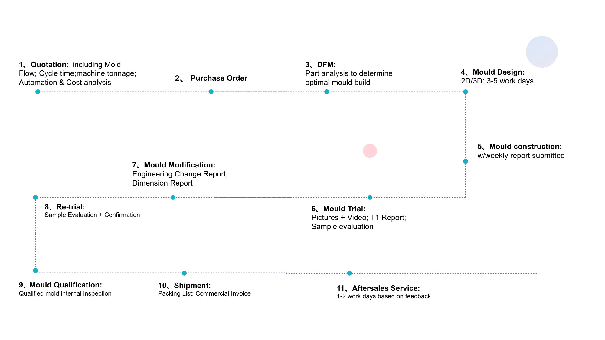
VIII. Manufacturing Process Flow for Thermostat Tube Mold and Molding
Ansix Tech follows a disciplined, documented manufacturing process flow from project initiation through final delivery. Each phase includes defined deliverables, quality gates, and customer touchpoints.
Phase 1: Project Initiation and Requirements Definition
Inputs Received:
3D CAD model of thermostat tube geometry (STEP, IGS, or native)
Material specification (PA66-GF30, PPS+40%GF, PEEK, etc.)
Annual volume projections and program duration
Quality requirements (tolerance standards, cosmetic grades, Cpk targets)
Regulatory requirements (IATF 16949, ISO 9001, UL flame rating, etc.)
Desired delivery schedule
Ansix Tech Deliverables:
Project plan with milestone dates
Preliminary mold configuration recommendation (number of cavities, mold type, gate type)
Preliminary material selection review
Quotation with commercial terms
Phase 2: DFM and Mold Flow Analysis
Detailed Analysis:
DFM review per Section VII above
Mold flow analysis per Section VII above
Deliverables to Customer:
DFM report documenting manufacturability recommendations
Mold flow simulation results (can be reviewed together in real-time session)
Recommended modifications to part geometry (if any)
Revised quotation reflecting any design changes
Mold design concept approval for next phase
Phase 3: Mold Design and Engineering
Detailed Engineering:
3D mold design assembly (all components modeled)
Thermal analysis of cooling circuit performance
Structural analysis of mold components under clamp and injection pressure
Selection of hot runner system (if specified) including gate location and nozzle selection
Design of ejection system and selection of ejector components
Deliverables to Customer:
Full 3D assembly model for review and approval
Cooling circuit layout for approval
Ejection system layout showing pin placement
Mold BOM with steel grade, source, and hardness documentation
Phase 4: Mold Manufacturing
Steel Preparation:
Rough machining of mold plates from stock (oversize allowance)
Heat treatment of selected components per specification
Stress-relief cycles for complex geometry components
Finish grinding of mounting surfaces and reference planes
Precision Machining:
Five-axis high-speed machining of core and cavity
EDM for deep ribs, narrow slots, and sharp internal corners
Wire EDM for contoured shut-offs and intricate core geometry
Jig grinding for precision guide pin and bushing fits
Mold Assembly:
Fit of core and cavity sets to 0.005 mm parting surface accuracy
Installation of guide pins, bushings, and return pins
Installation of cooling circuit fittings and manifold connections
Installation of hot runner system (manifold, nozzles, heaters, thermocouples)
Assembly of ejector system (ejector plate, pins, return springs)
Installation of limit switches, sensors, and connector interfaces
Mold Validation:
Dry-cycle testing to verify all moving components function correctly
Cooling circuit leak testing at 150% of rated pressure
Ejection system stroke verification
Dimensional measurement of all critical features on CMM
Comparison of measured dimensions to CAD nominal
Deliverables to Customer:
Mold as-built drawing package (2D and 3D)
CMM report for core and cavity dimensions
Cooling circuit flow and leak test results
Steel material certificates and heat treatment records
Photo documentation of mold assembly
Phase 5: Initial Sampling (T0 – T3)
T0 — First Shots / Mechanical Validation:
First shots taken on test press
Visual inspection of initial parts to identify obvious defects
Gate balance measurement (fill volume per cavity)
Verification of ejection reliability
Identification of any interference or binding issues
T1 — First Dimensional Validation:
Samples measured on CMM (minimum 5 shots per cavity)
First measurement results compared to nominal CAD model
Steel-safe modifications identified for dimension correction
Any required steel adjustment machined and re-sampled
T2 — Process Window Validation:
Process window DoE to identify robust parameter ranges
Optimization of cycle time while maintaining Cpk ≥1.33
Measurement of key dimensions across DoE runs
Cosmetic sampling and appearance verification
T3 — Production Run-Off Validation:
4–8 hour continuous run on target production equipment
Locked process parameters (temperature, pressure, speed, time)
Measurement of 32–50 consecutive shots for Cpk calculation
Cpk ≥1.33 demonstrated on all CTQ dimensions
Cycle time stability validated (≤5% variation)
Deliverables to Customer:
Sample parts from each trial iteration (T0, T1, T2, T3)
CMM reports for each cavity from T3 run-off
Process sheet documenting optimized parameters (locked recipe)
Cpk calculation table for each CTQ dimension
Pre-production validation summary
Phase 6: Production Launch
Pre-Production Run:
100–500 shot pre-production run on production equipment
Operator training on part removal and quality checks
Production packaging validation
Scrap rate tracking and root cause analysis
MES parameter lock and production batch setup
Production Qualification (PPAP / First Article):
ISIR (Initial Sample Inspection Report)
Dimension report (full part measurement, typically 30 parts)
Material certificates for production resin lot
Process capability report (Cpk for CTQ dimensions)
Appearance approval report
Functional test results (if applicable)
Phase 7: Ongoing Production Support
Scheduled Deliverables:
Cpk trend reporting (quarterly or per customer requirement)
Scrap rate tracking and reduction initiatives
Mold maintenance scheduling and execution
Material lot traceability
Continuous improvement proposals
Deliverables to Customer:
Production reports per agreed frequency
Quality data (Cpk, scrap, dimension capability)
Annual mold inspection and recertification
Maintenance recommendations based on actual cycle counts
Manufacturing Flow Summary
Phase Duration (Typical) Key Deliverables Quality Gate
Project Initiation 2–5 days Project plan, preliminary quote Customer sign-off
DFM & Mold Flow 5–10 days DFM report, simulation results Customer approval
Mold Design 10–20 days 3D assembly, cooling layout Customer approval
Mold Manufacturing 20–40 days Completed mold, CMM report Internal QA
Sampling (T0–T3) 7–15 days Sample parts, process sheet, Cpk Customer approval
Pre-Production 3–7 days PPAP, ISIR, Cpk verification Customer sign-off
Production Launch Ongoing Production batches, quality data Ongoing monitoring
IX. Quality Control and Assurance System
Quality control at Ansix Tech is not a department — it is a systems-integrated approach spanning incoming material inspection, in-process monitoring, outbound testing, and long-term capability tracking.
Incoming Quality Control (IQC)
Raw material resin testing: Verify material grade, manufacturer, and batch number. When required, test mechanical properties (tensile, flexural) and thermal properties (HDT, melt flow index) against material certificate.
Mold steel verification: Material certificates document steel grade, source, heat treatment, and hardness. CMM verification of dimension for critical components.
Supplier parts: Ejector pins, hot runner components, sensors, heaters, and purchased components verified against specifications before inventory receipt.
In-Process Quality Control (IPQC)
Process parameter monitoring: MES system logs all parameters against locked recipe. Alerts generated for any parameter deviation beyond control limits.
Inspection frequency: Per customer specification or per Ansix Tech standard (minimum 1 part per cavity per hour for dimensional verification, visual inspection at machine every 15–30 minutes).
Real-time defect detection: Vision inspection systems for high-volume lines. In-cavity pressure and temperature monitoring for critical dimensions. Ultrasonic wall thickness measurement for thin-wall components.
Reject tracking and segregation: Defective parts identified and segregated at the machine. Scrap categorized by defect type and root cause documented for process improvement.
Outgoing Quality Control (OQC)
Final inspection: CMM measurement of sample parts from each production batch (sample size per customer specification or AQL sampling plan).
Appearance inspection: Visual verification against approved appearance master samples. Surface roughness measurement for specified finishes. Color verification for pigmented materials (visual or spectrophotometer).
Functional testing: When required by customer, sample parts tested for pressure holding (leak testing), dimensional fit (assembly verification), or thermal cycle performance.
Packaging verification: Correct packaging configuration (part orientation, stacking, tray/box count). Labeling verification (part number, revision, batch number, quantity).
Process Capability Management
Cpk monitoring: Calculate Cpk for all CTQ dimensions on a production batch basis. Report capability trends quarterly or per customer requirement.
Process improvement trigger: When Cpk falls below 1.33 for any CTQ dimension (or customer-specified threshold), initiate root cause analysis and corrective action.
Control limits: MES system maintains Upper Control Limit (UCL) and Lower Control Limit (LCL) based on process capability study. Operator intervention required when measurements approach control limits.
Annual process revalidation: Full capability study performed annually or after significant process changes (new material lot, mold maintenance, equipment change).
Documentation and Traceability
Lot traceability: Each production batch linked to specific material lot, machine, process recipe, operator, and date/time stamp.
Measurement records: CMM reports stored permanently with batch number indexing. Optical inspection images retained for digital record.
Customer reporting: PPAP, ISIR, dimension reports, Cpk analysis, material certificates delivered per customer requirement (paper or electronic).
Quality certification: Ansix Tech maintains IATF 16949 and ISO 9001 certification. Additional certifications available upon request (ISO 13485 for medical applications, AS9100 for aerospace).
X. Packaging, Logistics, and Rapid Delivery
Packaging Solutions
Standard packaging: Plastic trays, anti-static bags, bulk boxes — selected based on part geometry, surface finish requirements, and handling constraints.
Custom packaging: Engineered trays for part orientation, stacking, and robotic pick-and-place integration. Custom dunnage and foam inserts for sensitive components.
Automated packaging: Integrated packaging cells automatically transfer parts from molding machines to packaging stations, reducing labor cost and eliminating handling damage.
Shipping protection: Polyethylene bag liners, desiccant packs (for moisture-sensitive materials), edge protectors, stretch wrap, corner guards.
Delivery Standards
Prototype tooling: 10–15 days from DFM approval
Production tooling (simple): 15–25 days
Production tooling (medium complexity): 25–35 days
Production tooling (complex): 35–45 days
Expedited service: Available at premium — validation steps not compromised
Logistics
Domestic shipping: LTL truck, full truckload, expedited courier (FedEx, UPS, DHL) depending on weight and urgency.
International shipping: Air freight (3–7 days), ocean freight (20–40 days) depending on volume and cost constraints. Full export documentation (commercial invoice, packing list, bill of lading, customs classification).
Inventory management: Consignment inventory programs available for high-volume, repeat orders. Kanban pull systems for JIT delivery. Safety stock management to cover supply chain disruptions.
Emergency Response
Mold repair: 24-hour turnaround for most repair types. Emergency weekend/night shifts for line-down situations.
Production overrun: 48–72 hour turnaround for urgent production quantities exceeding planned volume.
Engineering change: 5–10 day turnaround for steel-safe modifications (adding material to mold). 10–20 day turnaround for material-removal modifications (machining additional material). Customer approval required before implementation.
XI. Ansix Tech 28-Year Industry Experience: Delivering Reliability and Value
For 28 years, Ansix Tech has designed, manufactured, and molded precision plastic components for automotive, industrial, medical, and consumer applications. Our experience informs every aspect of thermostat tube manufacturing, from material selection to process optimization to quality validation.
Demonstrated Thermostat Tube Program Experience
Ansix Tech has successfully executed multiple thermostat tube and thermostat housing programs for automotive OEMs and Tier 1 suppliers, including:
PA66-GF35 thermostat housings for passenger car cooling systems
PPS + 40% GF thermostat tube assemblies for turbocharged engine applications
Two-shot molding of rigid thermostat bodies with LSR sealing elements
Multi-cavity (up to 8 impressions) high-volume production programs exceeding 2 million parts annually
Complex geometry components with internal flow passages and sealing interfaces
Engineering Expertise
Our engineering team brings:
28+ years of cumulative injection molding and mold making experience
Proficiency in mold flow simulation (Moldflow and equivalent software)
Expertise in high-performance polymer processing (PEEK, PPS, LCP, PEI)
IATF 16949 and ISO 9001 quality system implementation
Six Sigma and statistical process control methodologies
Customer Value Outcomes
When you partner with Ansix Tech for thermostat tube manufacturing, you achieve:
Reduced tooling cost: DFM optimization identifies design changes that simplify mold construction without compromising function — typically reducing tooling investment by 10–25%.
Lower per-part cost: Cycle time optimization reduces cooling time 15–25%, servo-electric energy savings reduce operating cost 50–80%, and runner optimization reduces material waste 15–30%.
Reduced risk: Mold flow analysis identifies and resolves manufacturability issues before steel is cut, eliminating sampling delays and production surprises. Cpk ≥1.33 validation demonstrates process capability before production release.
Faster time-to-market: Parallel engineering (DFM concurrent with mold design) compresses development timeline. Expedited sampling (T0–T3 in 7–15 days versus industry average 20–30 days) accelerates launch.
Cost Reduction: A Core Ansix Tech Competency
Ansix Tech reduces your total product cost through three integrated approaches:
Material Cost Optimization: We analyze alternative resin grades with equivalent performance at lower cost. For a thermostat housing program initially specified with PPS + 40% GF, we may substitute PA6T + 30% GF if operating temperature allows — reducing material cost 30–40% with minimal performance impact. We document the performance trade-offs so you make an informed decision.
Process Efficiency Optimization: Cycle time directly determines production capacity and per-part cost. Ansix Tech approaches cycle time reduction methodically — using mold flow analysis to identify cooling bottlenecks, designing conformal cooling to accelerate heat extraction, and implementing automated part handling to eliminate manual intervention delays. Typical cycle time reduction: 15–25% compared to conventional mold designs.
Production System Efficiency: Multi-cavitation, stack molds, and automated production cells increase output per machine hour without increasing labor cost. For high-volume thermostat tube programs, we design production systems that run lights-out — fully automated from resin drying through molding, part removal, quality inspection, and packaging. Labor cost per part reduced by 50–80%.
Total Cost of Ownership Transparency: We provide a documented cost model showing:
Tooling investment (mold cost, amortization schedule)
Per-part material cost
Per-part processing cost (machine hour rate, labor, utilities)
Per-part quality cost (inspection, scrap)
Per-part logistics cost (packaging, shipping, inventory carrying)
Total expected cost over program lifetime (typically 3–5 years)
This transparency enables fact-based sourcing decisions. When you compare Ansix Tech to lower-priced competitors, you see not just the initial tooling price, but the total delivered cost over your program‘s life — including factors like mold repair cost, production downtime risk, and scrap rate exposure. In most cases, Ansix Tech‘s total cost is lower despite a higher initial tooling investment, because our molds run longer, faster, and with fewer defects.
Dollar Savings Examples (Actual Customer Program Data, Representative Ranges):
Cost Category Industry Average Ansix Tech Achieved Annual Savings (1M parts)
Mold tooling cost (amortized over 500k parts) $0.09/part $0.06/part (premium steel, longer life) $30,000/year
Material waste (runner, scrap) 15% 8% (hot runner + process control) $70,000/year
Cycle time (seconds per part) 30 sec 22 sec (cooling optimization) $X based on machine hour rate
Scrap rate 5% 1.5% (process control, Cpk≥1.33) $87,500/year
Mold maintenance (annual) $8,000 $3,000 (premium steel, scheduled) $5,000/year
Estimated total annual savings — — $200,000+
Note: Actual savings vary based on part geometry, material selection, volume, and specific program requirements. Ansix Tech provides a customized cost reduction analysis for your thermostat tube program as part of our quotation process.
XII. Conclusion: Your Thermostat Tube Manufacturing Partner
Ansix Tech offers a complete, vertically integrated solution for thermostat tube manufacturing — from mold design and DFM analysis through molding, assembly, and delivery. Our 28 years of experience, precision equipment infrastructure, disciplined process control systems, and transparent cost modeling deliver measurable value:
Lower total cost of ownership through material optimization, cycle time reduction, and premium mold longevity
Reduced supply chain risk through vertical integration, in-house repair capability, and documented process capability
Faster time-to-market through parallel engineering, expedited sampling, and flexible production scheduling
Superior quality and consistency through MES-controlled processes, Cpk ≥1.33 validation, and ISO/IATF-certified quality systems
Our Commitment: A mold from Ansix Tech is not a block of steel — it is a revenue-generating asset designed for your production success. We design for flow balance, thermal stability, production robustness, and maintenance accessibility. We validate before shipping. And we support for the life of the tool.
We invite you to provide a 3D model and material specification for your thermostat tube component. Within 48 hours, we will return a preliminary DFM analysis, mold concept recommendation, commercial quotation, and estimated timeline.
Ansix Tech — Precision Without Compromise. Reliability Without Surprises.
Appendix: Technical Specifications Summary
Parameter Ansix Tech Capability
Mold precision capability ±0.002 mm (five-axis machining), ±0.003 mm tooling tolerance
Achievable part tolerances ±0.05 mm (standard), ±0.01–0.02 mm (precision), ±0.005 mm (fine-feature)
Mold materials S136, 2344/H13, 8407, NAK80, DC53, 420, SKD61
Mold life (unreinforced thermoplastics) 1,000,000+ cycles
Mold life (glass-reinforced materials) 500,000+ cycles
Injection machine range 30 tons – 4,000 tons clamping force
Process repeatability (servo-electric) ±0.00005 mm positioning resolution
Process repeatability (servo-hydraulic) ±0.05% of setpoint
Quality validation Cpk ≥1.33 on CTQ dimensions
Surface finish capability Ra ≤0.05 μm (mirror), Ra ≤0.2 μm (high-gloss)
Materials processed PA66-GF30/35/40, PA6T, PA9T, PPS+40%GF, PEEK, PC/ABS, PBT, PEI, LCP, LSR
Quality certifications IATF 16949, ISO 9001 (with additional per customer requirement)
For a detailed proposal tailored to your specific thermostat tube requirements, including DFM analysis, mold flow simulation, and commercial quotation, contact Ansix Tech today.
Ansix Tech Co Ltd
If you have any plans related to Thermostat tube , you can contact us at any time. We will turn your ideas into reality, let you realize your dreams, and obtain large orders from the market. Our contact information is info@ansixtech.com. Or contact our CTO, mail: stephen@ansixtech.com
#www.ansixtech.com #ansixtech.com #Thermostat tube #Thermostat tube moulds #Thermostat tube injection molding companies #Thermostat tube Canopy Mold injection mold companies #Ansix #Ansix moulds #Ansix china #Ansix tech china #Ansix tech company #Ansix facotry #Thermostat tube injection molding #Thermostat tube injection tools #Thermostat tube injection moulds #Thermostat tube plastic mould #Thermostat tube plastic tools #Ansix Tech #Ansix molds #Ansix injection molding #Ansix mold factory #injection molding Thermostat tube #Ansix mold factory #Thermostat tube china #Thermostat tube molds #injection factory #Thermostat tube injection molding #Thermostat tube injection molding factory #injection molding company #Thermostat tube injection mold companies #Thermostat tube#Thermostat tube mold limited #Ansix mold china #Ansix companies #Ansix company China #Thermostat tube facotry #Ansix Tech #Ansix Tech mould #Thermostat tube injection moulding #injection moulding company #Ansix Thermostat tube parts injection mold companies #medical injection molding companieschina #Thermostat tube china factory #Ansix moulding companies #Ansix molding company #Thermostat tube injection moulding facotry #Ansix Tech mold #Thermostat tube mould #Thermostat tube plastic injection molding #ansix plastic mold #Mold manufacturing #Thermostat tube parts manufacturing #Thermostat tube plastic parts factory #Thermostat tube injection parts mold #Thermostat tube PRECISION MANUFACTURING #Thermostat tube #China mold #Thermostat tube injection moulding china #Thermostat tube mould china #china precision mold #mold in china #Thermostat tube mold china #Precision molds #High-precision molds #Thermostat tube #Injection molds #Thermostat tube Factory #Thermostat tube Company #Super Large Injection Mold Factory #Large Tonnage Injection Molding Factory #Thermostat tube Company #Thermostat tube Factory #2800T Injection Molding Factory #3000 Ton Injection Molding #4500 Ton Injection Molding Factory #Large Mold Injection Molding #Large Plastic Mold Injection Molding Factory #Large Injection Mold Manufacturer #Plastic Mold Factory #Injection Mold #Plastic Mold