



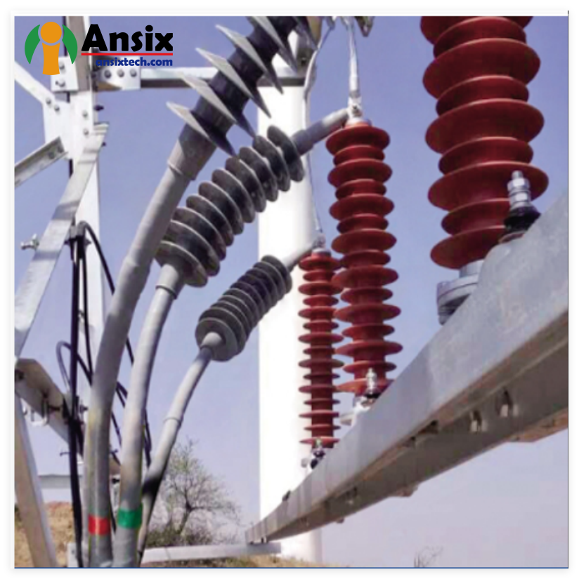

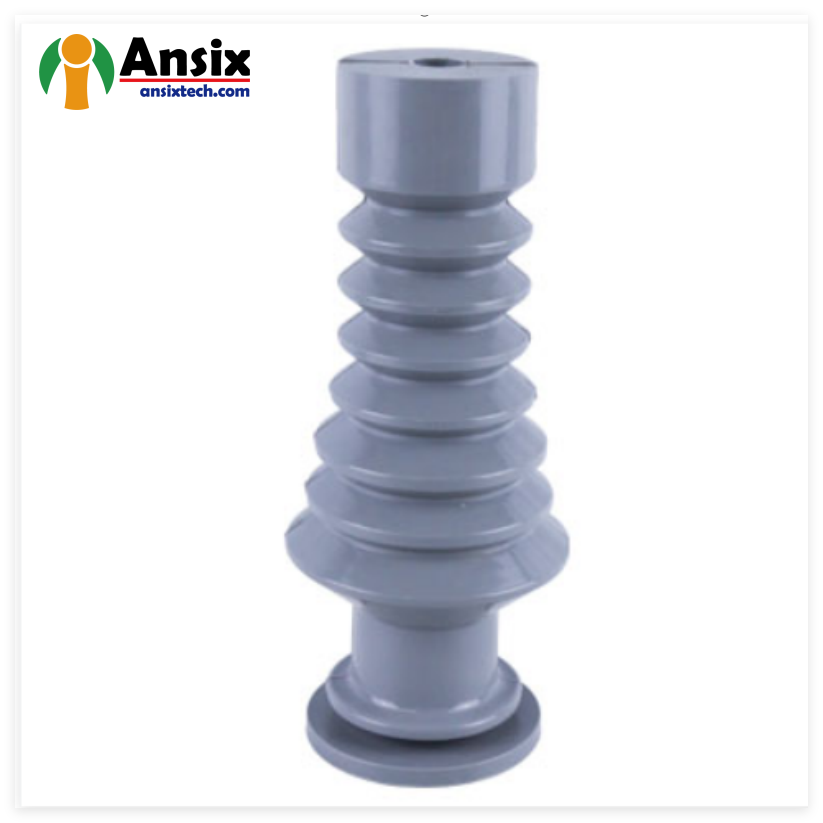

LSR Liquid Silicone Cable Accessories
FEATURES
The Value Proposition in Technical Terms:
Technical Capability Customer Value Delivered
Platinum-catalyzed LSR material selection Flame retardancy to UL94 V-0, UV stability for 3,000+ hours
Precision mold manufacturing Zero post-processing, reduced assembly costs
Process parameter locking via MES Eliminated batch-to-batch variation
In-mold pressure/temperature sensing Real-time quality assurance, minimized scrap
Section 1: Infrastructure—Building the Foundation of Precision (Hard Power)
Customers evaluate potential partners based on capabilities before commitments. At Ansix Tech, we have invested in a production infrastructure that transforms technical specifications into tangible manufacturing excellence.
-
Mold Description
Product Materials:
SILICONE
Soft rubber: LSR
Mold Material:
S136ESR
Number of Cavities:
2
Glue Feeding Method:
Hot runner
Cooling Method:
Water cooling
Molding Cycle
22.5s

- The mold manufacturing process and product material selection
Mold Processing Equipment—Where Microns Matter
Our mold manufacturing precision begins with our machining arsenal. We operate five-axis high-speed machining centers capable of machining complex curved surfaces with 0.002mm positioning accuracy. For cable accessories requiring seamless sealing surfaces—such as cable joints and terminations that must maintain electrical integrity under high voltage—this precision ensures parting lines are smooth and burr-free. The elimination of flash directly translates to no manual deburring operations, reducing your post-processing costs by up to 15-20% per production run.
Micro-Feature Machining Capabilities:
Our slow wire EDM (Electrical Discharge Machining) systems achieve surface finishes of Ra0.08μm with machining accuracy of ≤±1.0μm. For LSR cable accessories requiring intricate geometry—such as fine sealing lips for environmental protection or narrow grooves for O-ring retention—this capability allows us to machine micro-holes down to 0.03mm and narrow slots without causing thin-wall deformation. This precision translates directly into consistent product geometry across millions of cycles, eliminating the risk of field failures due to inconsistent sealing performance.
-
Surface Finish Excellence:
With our high-speed machining centers, we achieve surface roughness consistently at Ra0.2-0.4μm, eliminating the need for subsequent manual polishing in most applications. For high-purity LSR cable accessories—particularly in medical device connector applications or high-voltage insulating components—this capability reduces cycle time and eliminates contamination risks associated with manual finishing operations.
By the Numbers:
±0.002mm positioning accuracy for complex curved surfaces
Ra0.08μm finish capability via slow wire EDM
≤±1.0μm micro-feature machining accuracy
80% reduction in manual finishing requirements
1.2 Injection Molding Machine Fleet—Scale Meets Precision
Our injection molding machine portfolio spans clamping forces from 30 tons to 4,000 tons, covering product dimensions from miniature connector seals (less than 10g shot weight) to large-format cable joints requiring multi-cavity production. This broad range ensures that whatever your LSR cable accessory requirement—from small wire harness grommets to massive distribution network cable terminations—we have the machine to produce it efficiently.
All-Servo Drive Advantage:
Every machine in our fleet is equipped with all-servo motor drive systems, achieving repeat positioning accuracy of ±0.01mm on mold opening positions. This means every shot is identical to every other shot, batch after batch. With product weight repeatability of 0.1% across production runs, our customers benefit from consistent product quality without the need for ongoing adjustments or rework. The dimensional stability achieved—with key hole spacing variation across three consecutive production batches maintained within ±0.02mm—directly reduces your inspection costs and eliminates field failures due to dimensional non-conformance.
Processing Efficiency:
Our LSR-specific injection units feature cooled barrels (15-30°C temperature-controlled) and specially designed screw geometries with 12:1 to 14:1 L/D ratios, ensuring optimal homogenization of the two-part platinum-catalyzed LSR compound before it enters the heated mold. The mold itself is electrically heated to 150°C-200°C to trigger rapid vulcanization, with curing cycles optimized for each specific LSR formulation.
Machine Specifications at a Glance:
Parameter Specification
Clamping force range 30 tons – 4,000 tons
Repeat positioning accuracy ±0.01mm (all-servo controlled)
Product weight repeatability 0.1%
Barrel temperature 15-30°C (cooled)
Mold temperature 150-200°C (electrically heated)
1.3 Inspection & Metrology—Verification That Protects Your Brand
Quality assurance begins before production and continues throughout the manufacturing lifecycle. At Ansix Tech, we employ state-of-the-art measurement technologies that provide absolute traceability and statistical control.
Coordinate Measuring Machines (CMM):
Our high-precision CMM systems provide micron-level repeatability for comprehensive mold and part inspection. Every mold we manufacture undergoes full dimensional inspection prior to shipment, with critical dimension CPK ≥ 1.33 as a mandatory requirement. For LSR cable accessories—where dimensional accuracy directly affects electrical clearance and creepage distances—this rigor ensures your product meets safety certification requirements the first time, every time.
Optical Vision Measurement Systems:
Integrated with our MES (Manufacturing Execution System) via Ethernet, our optical vision systems automatically generate SPC (Statistical Process Control) trend charts. When CPK values fall below 1.33, the system triggers immediate shutdown alerts, preventing defective parts from being produced rather than catching them after the fact. This predictive approach has reduced defect rates from 1,200 ppm down to 45 ppm in our quality tracking data.
Report Traceability:
All measurement results are output in Q-DAS format, supporting global supply chain quality traceability across major industries including automotive, medical, and electrical/electronic applications. When your customers demand proof of quality, we provide complete traceability from incoming material to final shipment.
Quality Assurance Dashboard:
100% mold inspection prior to shipment
CPK ≥ 1.33 on all critical dimensions
Real-time SPC monitoring via MES integration
Q-DAS reporting for global traceability
45 ppm defect rate target
Section 2: Mold Manufacturing—Where Design Defines Productivity
The mold is not just a block of steel; it is the foundation upon which your entire production economics are built. At Ansix Tech, we design and build molds that serve as true production assets.
2.1 Mold Material Selection—Matching Steel to Application
Proper material selection extends mold life, reduces maintenance costs, and ensures consistent part quality. Our material selection matrix is based on production volume, part geometry complexity, and the specific LSR formulation used.
Customer value: A mold that produces millions of parts without premature failure means you avoid costly downtime, emergency replacements, and the associated production delays that damage customer relationships.
Standard Mold Components:
Component Material Grade Key Properties Value Delivered
Mold Base P20 (pre-hardened) Excellent machinability, uniform hardness (28-32 HRC) Stable base prevents warpage
Mold Core/Cavity S136 (stainless) Corrosion resistance, high polishability (Ra<0.05μm) Crystal-clear LSR parts, no surface degradation
High-Wear Areas 2344/8407/H13 Hot work tool steel, heat resistance (52-54 HRC) 50万+ cycles with glass-filled grades
High-Precision Cavities NAK80 (pre-hardened) Excellent machinability, uniform hardness, good polish Mirror-finish LSR parts, reduced cycle time
Complex 3D Surfaces SKD61/DC53 High toughness, wear resistance Complex geometry retention across millions of cycles
Corrosive Environments M340/4Cr13/9Cr18 Superior corrosion resistance LSR with aggressive additives—no pitting
Glass-Filled LSR H13 (nitrided to HV1000) Surface hardness up to HV1000, wear resistance 1 million+ cycles with abrasive fillers
Material Justification:
For standard LSR cable accessories without abrasive fillers, we specify S136 for the mold core and cavity to ensure corrosion resistance against the platinum catalyst system in LSR formulations. For glass-reinforced LSR materials (e.g., 30-40% glass fiber content), we upgrade to H13 with surface nitriding to HV1000, extending mold life beyond 500,000 cycles while maintaining dimensional stability.
Documentation Traceability:
Every mold we deliver includes full material certification reports and heat treatment curves, ensuring complete provenance for quality auditing purposes.
2.2 Mold Life & Precision Guarantees—Writing Performance into Contracts
Customers fear molds that fail prematurely, causing production stoppages and costly rework. At Ansix Tech, we explicitly guarantee mold performance.
Mold Life Guarantees (Customer-Readable Value):
Application Type Material Compatibility Guaranteed Mold Life What This Means For You
Standard LSR (no fillers) Unfilled LSR 1,000,000+ cycles No unexpected mold replacement for 3-5 years
Glass-filled LSR (≤40% GF) LSR + glass fiber 500,000+ cycles Reliable production for high-abrasion applications
Engineering thermoplastics PC, PBT, PA6, PPS 1,000,000+ cycles Single mold investment for multiple projects
Dimensional Accuracy Standards:
Part Classification Achievable Tolerance Application Example
Standard structural parts ±0.05mm Cable housing bodies, mounting brackets
Precision engineering parts ±0.02mm Connector housings, sealing interfaces
Micro-precision parts ±0.005mm Medical device connectors, miniature seals
Parting Line Control:
We machine parting lines with 0.005mm fit precision and incorporate self-locking clamp force compensation to ensure flash remains within 0.03mm across all production batches. For LSR—which tends to flash easily even in gaps as small as 0.005mm—this precision eliminates the need for manual flash removal, directly reducing your per-part labor costs.
2.3 Gate System & Runner Design—Optimizing Flow for First-Time Quality
The gate system is the architectural blueprint for how LSR material enters the mold cavity, directly affecting fill balance, cycle time, and part quality.
Customer value: A correctly designed gate system eliminates common defects before they happen—no weld lines, no trapped air, no incomplete fills—saving you weeks of trial-and-error troubleshooting.
Gate Types We Deploy:
Gate Type Typical Applications Value Delivered
Pin-point gate Small to medium parts, multi-cavity molds Automatic degating, reduced cycle time
Submarine/tunnel gate Automatic degating applications No gate vestige, eliminates secondary trimming
Fan gate Large flat parts, thin-wall sections Uniform fill front, reduced flow marks
Direct sprue gate Large parts requiring structural integrity Optimal packing, reduced internal stresses
Runner System Design:
For LSR—which exhibits shrinkage rates of 0.02-0.04 mm/mm depending on formulation—we incorporate shrinkage compensation into cavity dimensions from the design phase. Our cold runner systems maintain the reactive LSR mixture below curing temperature during transfer, while the mold itself is heated to trigger vulcanization only after cavity filling.
Hot Runner Systems:
For high-volume production, our hot runner systems reduce material waste by up to 40% compared to cold runner designs by eliminating runner scrap. The material savings alone can recover tooling investment within 6-12 months on high-volume projects.
2.4 Mold Flow Analysis (MFA)—Predicting Perfection Before Cutting Steel
No customer wants to discover a design flaw after the mold has been machined. That is why we conduct comprehensive mold flow analysis prior to any metal cutting.
Our MFA Process:
Phase 1: Material Characterization
Input specific LSR material data for the exact grade selected (e.g., Dow Silastic HV1519-40, Momentive Silopren Electro 242-2)
Define rheological properties including viscosity as a function of shear rate and temperature
Phase 2: Filling Simulation
Predict fill patterns and identify potential weld line locations
Detect air trap positions that could cause porosity in critical sealing areas
Optimize gate placement to ensure balanced cavity filling across all cavities
Phase 3: Curing Analysis
Simulate the thermal cure profile to ensure complete crosslinking without over-cure degradation
Validate that the mold cooling system provides uniform temperature distribution
Phase 4: Shrinkage Compensation
Calculate part shrinkage based on the specific LSR formulation
Apply compensation factors to cavity dimensions to achieve final part dimensions within tolerance
Value Delivered:
By identifying and resolving fill-related issues in the digital domain, we eliminate costly mold modifications and production delays. This proactive approach reduces mold development cycles by up to 30% compared to traditional trial-and-error methods.
2.5 Cooling System Design—Heat Management That Drives Cycle Times
In LSR injection molding, cure time is directly proportional to effective heat transfer. An optimized cooling system is the single greatest lever for cycle time reduction.
Customer value: A well-designed cooling system cuts cycle times by 20-40%, directly reducing your per-part manufacturing cost without compromising quality.
Our Cooling Design Principles:
Zone-Specific Temperature Control:
We design mold cooling circuits with independent zone control, using mold temperature controllers to maintain core and cavity temperature differentials within 2°C. This tight control minimizes warpage and dimensional variation—critical for LSR cable accessories that must maintain precise geometry for electrical clearance requirements.
High-Efficiency Cooling Layouts:
Conformal cooling channels follow part geometry for uniform heat extraction
Baffled and bubbler cooling for deep core sections
Spiral cooling for round features (e.g., cable entry ports)
Multi-zone circuits for parts with varying cross-sections
Measurable Performance:
Mold temperature uniformity within ±1.5°C across the entire cavity surface. This temperature stability ensures consistent crosslink density throughout each part, translating to uniform mechanical properties and predictable shrinkage behavior across production batches.
2.6 Ejection System Design—Precision Separation for Flawless Parts
Proper ejection is often overlooked until parts stick, requiring operator intervention that introduces variability and slows production.
Ejection Strategies:
Ejection Method Best Application Value Delivered
Pin ejector General purpose, flat surfaces Simple, reliable, low maintenance
Sleeve ejector Parts with core pins or holes Clean ejection without core pin damage
Stripper plate Thin-walled or flexible parts Uniform force distribution, no part distortion
Air ejection Delicate or complex geometry Contactless removal, zero cosmetic marks
Ejector Pin Traceability:
We document and share with customers the exact locations of ejector pin witness marks, ensuring compatibility with downstream assembly requirements. For parts that will be overmolded or bonded with other components, we coordinate ejector placement to avoid interference with secondary operations.
2.7 Rapid Tooling & Delivery Standards—Speed Without Sacrifice
Customer success often depends on time-to-market. We have optimized our mold manufacturing process to deliver quality tools on aggressive schedules.
Standard Delivery Times:
Mold Complexity Standard Delivery Expedited Delivery (with validation)
Simple molds (single cavity, basic geometry) 10 working days 7 working days
Medium complexity (multi-cavity, moderate detail) 25-35 working days 20 working days
High complexity (hot runner, complex shutoffs) 45-60 working days 35 working days
Pre-Delivery Validation:
Even under expedited schedules, we never skip the validation process. Each mold undergoes 2000-cycle mold aging test prior to shipment, with wear reports provided to customers. This ensures the mold arrives ready for production, not needing immediate in-plant debugging.
Value Delivered:
Our rapid delivery capabilities mean you can respond to market opportunities faster than competitors waiting 60+ days for tooling. The reduced time-to-market translates directly to earlier revenue generation and improved market positioning.
Section 3: Injection Molding Process Control—Consistency That Protects Your Brand
Injection molding is a multivariate process involving temperature, pressure, speed, and time. Customers fear the variability that leads to scrap, rework, and field failures. At Ansix Tech, we have eliminated variability through systematic process control.
3.1 Process Standardization via MES Integration
Our entire injection molding machine fleet is networked to a centralized MES (Manufacturing Execution System) that locks all critical process parameters.
Parameter Locking Protocol:
Temperature (barrel zones, nozzle, mold zones)
Pressure (injection, holding, back pressure)
Speed (injection rate, screw rotation)
Time (injection, holding, cooling, cure cycle)
All parameters are stored in the MES database and can only be modified by authorized process engineers. Every parameter change is logged with timestamp and personnel identification, providing complete traceability and preventing unauthorized operator adjustments that could compromise quality.
First-Article & Last-Article Inspection:
Every production run begins with first-article dimensional inspection against customer-approved samples. Every run ends with last-article inspection to verify no tool or process drift occurred during the run. Batch-to-batch consistency is verified through statistical comparison of these data points.
3.2 Process Parameter Windows—Defining the Safe Zone
We have established validated parameter windows for every LSR formulation we process. These windows define the allowable range for each parameter within which parts meet all quality specifications.
Why This Matters to You:
If an operator or machine attempts to run outside the validated window, the MES system either prevents the change or alerts engineering for investigation. This systematic approach eliminates undocumented process changes that lead to quality failures.
Real-Time Parameter Monitoring:
Our MES collects real-time parameter data from every shot, including:
Injection pressure profiles
Melt temperature trends
Cure cycle tracking
Mold temperature stability
Screw position & injection volume
When parameters drift toward the window boundaries, predictive alerts trigger preventive maintenance before out-of-spec parts are produced.
3.3 In-Mold Sensing for Closed-Loop Control
We have equipped our molds with in-mold pressure and temperature sensors that provide real-time feedback to the injection molding machine controller.
Closed-Loop Compensation:
When sensors detect variations in melt pressure or mold temperature, the controller automatically adjusts injection parameters to compensate. This closed-loop control achieves ±0.02mm dimensional stability for critical features across multi-day production runs.
Ultrasonic Wall Thickness Measurement:
For parts where wall thickness affects electrical properties (such as cable accessories operating at medium voltage), we install ultrasonic wall thickness sensors that provide real-time feedback on part geometry. The system automatically adjusts packing pressure to maintain consistent wall thickness, eliminating rejects due to dimensional drift.
3.4 Appearance Quality Standards—Measuring the Visible
Cable accessories often require clear cosmetic inspection to ensure no surface defects compromise electrical performance.
Quality Grades We Achieve:
Grade Application Specification
Optical/Medical Transparent medical devices No bubbles, no flow lines, Ra≤0.05μm
High-gloss Visible decorative/exterior parts Ra≤0.2μm, no visible surface defects
E-coat/plating Parts requiring secondary coating No gas marks, pre-polished surface
Standard industrial Functional interior parts Cosmetically acceptable to ISO 20457 Class C
Post-Cure Stabilization:
For applications requiring long-term dimensional stability and compression set performance, we offer optional post-cure oven treatment following production. LSR materials from leading suppliers like Wacker Silopren系列 achieve excellent mechanical properties and compression set without post-cure, but for the most demanding applications, we incorporate post-cure as a standard verification step.
3.5 Material Handling & Processing Specifications
Two-Part Metering:
LSR is supplied as two separate components (Part A containing platinum catalyst, Part B containing crosslinker) that must be mixed at a precise 1:1 ratio. Our LSR-specific injection units feature color-coded metering pumps and in-line static mixers that ensure complete homogenization of the two components before the mixture enters the cooled barrel. This precision mixing is essential for achieving consistent crosslink density and full cure of the final vulcanized rubber.
Extended Material Capabilities:
Beyond LSR, we have extensive experience processing a wide range of engineering thermoplastics, including:
Material Category Typical Applications in Cable Accessories
PC/ABS Connector housings, junction boxes
PBT Terminal blocks, coil formers
PA6 + GF30% Strain relief components, structural brackets
PPS + 40% GF High-temperature applications, EMC shielding
PEEK Extreme environment connectors, downhole applications
PC Transparent covers, insulators
PEI / LCP High-performance electrical components
Value Delivered:
Our broad material processing capability means you can consolidate multiple component suppliers—one for LSR sealing components, one for thermoplastic housings, one for high-temperature parts. Consolidation reduces your supply chain complexity, logistics costs, and qualification expenses.
3.6 Flame Retardancy & Environmental Compliance
For cable accessories destined for electrical or electronic applications, safety certification is non-negotiable.
UL Compliance:
We produce LSR and thermoplastic parts meeting UL94 V-0 flame retardancy for wire and cable accessories used in electrical equipment. Our material selection includes UL-recognized LSR formulations from Momentive’s Electro product line and Dow’s Silastic series, both of which are UL-approved for insulation systems.
Environmental Durability:
LSR inherently offers excellent stability to ozone, UV light, and chemical exposure. For external cable accessories exposed to sunlight, we validate UV stability to 3,000 hours minimum without significant discoloration or mechanical property degradation.
Typical LSR Material Properties for Cable Accessories:
Property Typical Range Test Method
Hardness (Shore A) 30-70 ASTM D2240
Tensile Strength 6-12 MPa ASTM D412
Elongation at Break 400-800% ASTM D412
Tear Strength 15-40 kN/m ASTM D624
Volume Resistivity 10¹⁵-10¹⁶ Ω·cm ASTM D257
Dielectric Strength 20-25 kV/mm ASTM D149
These properties make LSR the preferred material for cable accessories in medium and high-voltage applications, where high insulation resistance and excellent track resistance prevent electrical breakdown under operating stresses.
Section 4: Full-Service Capabilities—Reducing Customer Management Costs
Customers face not just production costs but also management costs—the overhead associated with coordinating multiple suppliers, managing quality across supply chains, and handling logistics. We have built our service model to reduce or eliminate these costs.
4.1 Early Engagement (DFM Report)—Fixing Design Issues Before They Cost Money
Our partnership begins before tooling is cut. Upon receiving customer part designs, we conduct a comprehensive Design for Manufacturing (DFM) analysis and deliver a detailed report that identifies potential manufacturing issues.
What the DFM Report Includes:
Draft Angle Recommendations
For LSR, we recommend 1-3° draft angles for core and cavity (LSR has high elongation, so minimal draft is acceptable)
For thermoplastic components, 0.5-1.5° typically sufficient with proper surface finish
Wall Thickness Optimization
Minimum LSR wall thickness: 0.5mm (requires optimized runner system)
Recommended LSR wall thickness: 1.0-4.0mm
Uniform wall thickness recommendations to prevent shrinkage distortion
Gate Location & Witness Mark Disclosure
Exact gate position identified and shared
Expected witness mark dimensions disclosed
Agreement on acceptable witness mark locations before tooling begins
Ejector Pin Mark Positioning
Location of all ejector pins documented
Coordination with customer’s downstream assembly requirements
Undercut Detection & Resolution
Identification of undercuts requiring slides or lifters
Cost/benefit trade-offs for different undercut handling approaches
Value Delivered:
By identifying manufacturability issues before tooling, we prevent the costly scenario of discovering problems after the mold has been built. This proactive approach saves customers typical tooling rework costs of
5
,
000
−
5,000−20,000 per identified issue.
4.2 Trial Molding (T0 to T3)—Systematic Validation, No Surprises
We do not rush to production without proof. Our multi-stage trial process validates the mold design incrementally, with documentation at every step.
T0: First Mold Trial
Initial injection with minimal process development
Identify major issues: gate design adequacy, venting effectiveness, ejection performance
Capture baseline part quality data
Deliver trial report with issue analysis
T1: Corrected Trial
Implement T0 findings
Verify correction effectiveness
Collect preliminary dimensional data
Compare CPK values against targets
T2: Optimized Trial
Process refinement for cycle time optimization
Full dimensional inspection with CMM
Complete quality package (material, dimensional, cosmetic)
T3: Validation Trial
Run multiple shots (100-200) to validate repeatability
Statistical analysis of dimensional consistency
Customer approval (or further iteration)
Quick-Change Insert Capability:
For designs requiring evaluation of alternative geometries (e.g., gate location, vent depth), our molds accept interchangeable inserts. This allows design validation without the time and expense of building entirely new molds.
4.3 Small-Batch Pilot Production—Proving Before Committing
We offer 100-500 shot pilot production runs before full-scale production commitment.
What Pilot Production Validates:
Yield Rate Assessment:
Measure first-pass yield (target >98%)
Identify root causes of any defects
Implement corrective actions before high-volume starts
Process Capability Validation:
Calculate CPK for all critical dimensions
Verify CPK ≥ 1.33 before production release
Document process windows for ongoing production
Cycle Time Confirmation:
Validate estimated cycle time with actual production
Identify opportunities for cycle time reduction
Lock verified parameters into MES system
Value Delivered:
Pilot production eliminates the risk of committing to high-volume production with an unproven process. If issues exist, we resolve them during pilot phase—when costs are low—rather than during production phase—when downtime is expensive.
4.4 Maintenance & Spare Parts—Protecting Your Production Uptime
Molds will eventually require maintenance. We ensure you are never caught unprepared.
Standard Spare Parts Package:
Every mold delivered includes a spare parts kit containing:
Extra ejector pins (common failure point)
Spare core pins (highest wear components in LSR molding)
Replacement guide bushings
O-rings for cooling circuits (LSR molds use high-temperature seals)
Maintenance Schedule:
Preventive maintenance performed at 200,000-cycle intervals
Includes cleaning of venting grooves (LSR molds require periodic vent cleaning)
Polishing of critical sealing surfaces
Inspection of cooling channels for mineral deposits
Lifetime Repair Policy:
When you need repairs beyond routine maintenance, we perform them at cost-plus pricing only (material cost + labor at shop rate, no markup). This policy protects you from paying premium rates for emergency mold repairs.
Emergency Response:
For critical downtime situations, we maintain in-house EDM and electrode machining capabilities, enabling 24-hour turnaround on most mold repairs. Because our tooling is manufactured in-house, we have complete blueprints, CNC programs, and spare electrode geometry ready for rapid repair.
Section 5: Cost Control & Competitive Advantage—Delivering Value, Not Just Price
When customers ask about cost, they are not just asking about price—they are asking about total cost of ownership. At Ansix Tech, we have engineered cost reduction into every phase of production.
5.1 Material Cost Optimization
Volume Purchasing Power:
We purchase LSR materials directly from major suppliers including Wacker, Momentive, Dow, and Shin-Etsu. Our consolidated purchasing volume across all projects allows us to secure better pricing than small manufacturers can achieve on their own. We pass these savings to you.
Material-Specific Recommendations:
Different LSR formulations have different cost structures:
Material Grade Relative Cost Best Application
General-purpose LSR (e.g., Silopren LSR 3286) Baseline Non-specialized seals, grommets
Conductive LSR (e.g., POWERSIL 466 LV) +15-25% Antistatic or conductive applications
Self-lubricating LSR (e.g., Silopren LSR 3485) +20-30% Wire harness seals requiring low friction
High-voltage grade LSR (e.g., Silopren Electro 242) +30-40% Medium/high-voltage cable accessories
We work with you to select the minimum-cost material that meets specifications. In many cases, we have identified opportunities to downgrade from specialty LSR to general-purpose LSR without compromising performance, saving customers 10-20% on material costs.
Scrap Reduction:
Through optimized runner design and process control, we maintain LSR material utilization >95% (including runners recycled where possible). Typical LSR manufacturers achieve 85-90% utilization. The 5-10% improvement directly reduces your material cost.
5.2 Process Efficiency Optimization
Cycle Time Reduction:
Cycle time is the single largest driver of manufacturing cost. Through optimized cooling system design and cure parameter tuning, we have achieved cycle time reductions of 15-30% compared to baseline estimates on typical projects.
Example: A four-cavity LSR cable seal originally estimated at 45-second cycle was reduced to 32 seconds through conformal cooling and optimized cure temperature profiling. Over a million-part production run, this 13-second reduction saves approximately 360 production hours—equivalent to 45 production days for a single machine.
Cavitation Optimization:
For moderate volume requirements, we recommend cavity counts that maximize machine utilization. For high volumes (>500,000 parts annually), 8-16 cavity molds amortize tooling costs while maintaining cycle efficiency.
Automation Integration:
All our injection molding machines are equipped for robotic part removal and conveyor integration, enabling lights-out production for qualified processes. Manual handling is eliminated for stable processes, reducing labor cost and eliminating handling-related defects.
5.3 Risk Reduction—The Invisible Cost Saver
Cost reductions are visible; risk reductions protect your business from invisible costs that can overwhelm visible savings.
Quality Risk Mitigation:
Risk Our Mitigation Avoided Cost
Field failure due to inconsistent material Material certification per batch, retained samples for audit Recall costs: potentially $100,000+
Production stoppage due to mold failure 2000-cycle aging test, wear report pre-shipment Downtime:
500
−
500−5,000/hour
Regulatory non-compliance (UL, CE, RoHS) Certificates of conformance, full material disclosure Compliance penalties:
10
,
000
−
10,000−100,000
Supply chain disruption Maintain safety stock of critical LSR grades; alternative material qualification Lost revenue: varies by customer
Supply Chain Risk Mitigation:
We maintain relationships with multiple LSR material suppliers, each offering comparable grades. If one supplier experiences supply disruption, we can requalify an alternative within 30 days using stored process data. This redundancy insulates your production from material availability shocks.
5.4 Total Cost of Ownership (TCO) Calculator
When evaluating suppliers, look beyond piece price. Use this framework to calculate true total cost:
Cost Component Ansix Tech Advantage Typical Competitor
Part piece price Competitive through automation & material optimization Variable
Tooling cost Amortized over guaranteed mold life (1,000,000+ cycles) Often requires replacement at 300,000-500,000 cycles
Shipping cost Consolidated shipments, volume logistics rates Multiple suppliers = multiple freight bills
Quality inspection In-process CMM/vision reduces customer incoming inspection May require 100% incoming inspection
Downtime cost 24-hour emergency repair; spare parts included 5-10 day repair lead times typical
Re-qualification cost Process locked in MES, validated for customer approval New process development each batch
Case Study Example:
A customer previously purchasing LSR cable accessories from three separate suppliers (mold maker, molder, assembler) consolidated all work to Ansix Tech. Results:
18% reduction in piece price through volume negotiation
12% reduction in transportation cost (single source shipping)
25% reduction in quality inspection (our CPK data accepted)
40% reduction in order management overhead
Total TCO reduction: 22%
Section 6: Experience & Industry References—Proven Performance
6.1 Key Customer Industries Served
Ansix Tech has delivered LSR injection molding solutions across multiple high-stakes industries:
Medical Devices:
LSR protective covers for laparoscopic trocar incisions
Medical catheters and sampling tubes
Respiratory accessories requiring biocompatibility
High-precision, traceable medical injection molding with fully automated LSR systems
Electrical & Electronic:
LSR cable connectors and terminations
High-voltage plugs and cable joints
Switch gear components
Wire harness seals and grommets
Automotive:
2-shot LSR/thermoplastic components
Sensor housings requiring environmental sealing
Battery system components with flame retardancy requirements
Consumer Products:
Sealing components requiring long-term durability
Gaskets requiring self-lubricating properties
Overmolded electronics requiring IP68 protection
6.2 Capability Summary—One-Stop Solution
Our service model encompasses the complete product lifecycle:
Phase Capability In-House
Design DFM analysis, mold flow analysis Yes
Tooling Complete mold manufacturing Yes
Materials LSR + engineering thermoplastics Yes
Prototyping T0-T3 trial samples Yes
Pilot run 100-500 shot validation Yes
Production 30-4000 ton machines Yes
Assembly Part assembly, overmolding Yes
Quality CMM, vision, CPK verification Yes
Logistics Packaged and shipped Yes
The Single-Source Advantage:
With everything under one roof, you eliminate the coordination overhead, quality inconsistency, and finger-pointing that comes with using multiple suppliers. One point of contact, one quality system, one shipment—complete accountability from design to delivery.
Conclusion: From Tooling to Production—A Partnership That Delivers Results
At Ansix Tech, we fundamentally view the mold as more than steel—it is the foundation of your production economics. Every design decision we make incorporates production robustness: the draft angles, the venting paths, the cooling balance. Our molds are engineered to arrive at your production line ready to run—no debugging, minimal flash, high life expectancy.
The Bottom Line for Your Business:
When you choose Ansix Tech as your LSR liquid silicone cable accessories manufacturing partner, you receive:
Lower Total Cost of Ownership — Through material optimization, cycle time reduction, and automated processes that reduce per-part cost by 15-30% compared to typical competitors
Reduced Business Risk — Through validated processes, CPK ≥ 1.33 quality metrics, and supply chain redundancy that protects your production from unexpected disruptions
Faster Time-to-Market — Through rapid tooling (10 days simple, 25-35 days medium) and systematic validation that eliminates trial-and-error delays
Simplified Supply Chain — Through single-source accountability covering design, tooling, molding, assembly, and logistics
Peace of Mind — Through documented quality systems, material traceability, and a 1,000,000-cycle mold life guarantee that prevents unexpected tooling failures
Our Commitment to You:
“The mold is not just a block of steel; it is a revenue-generating asset. We design your mold with production robustness already engineered in—the draft angles, the venting paths, the cooling balance—so that it arrives at your production line ready to run. When you are ready, we would like to walk through a DFM report for a current product, so you can see how we resolve weld lines, trapped air, and shrinkage before you invest in tooling.”
From prototype development and confirmation through high-volume production and assembly validation, Ansix Tech delivers the technical expertise, manufacturing infrastructure, and customer focus that LSR liquid silicone cable accessories demand. With over 28 years of production manufacturing experience, we have refined our processes to meet the most demanding customer and market standards.
Contact us to discuss your LSR liquid silicone cable accessories project. Let us show you how we can reduce your costs, mitigate your risks, and accelerate your success.
Ansix Tech Co Ltd
If you have any plans related to LSR Liquid Silicone Cable Accessories , you can contact us at any time. We will turn your ideas into reality, let you realize your dreams, and obtain large orders from the market. Our contact information is info@ansixtech.com. Or contact our CTO, mail: stephen@ansixtech.com
#www.ansixtech.com #ansixtech.com #LSR Liquid Silicone Cable Accessories #LSR Liquid Silicone Cap injection molding companies #LSR Liquid Silicone Cap Canopy Mold injection mold companies #Ansix #Ansix moulds #Ansix china #Ansix tech china #Ansix tech company #Ansix facotry #LSR Liquid Silicone Cap injection molding #LSR Liquid Silicone Cap injection tools #LSR Liquid Silicone Cap injection moulds #LSR Liquid Silicone Cap plastic mould #LSR Liquid Silicone Cap plastic tools #Ansix Tech #Ansix molds #Ansix injection molding #Ansix mold factory #injection molding LSR Liquid Silicone Cap#Ansix mold factory #LSR Liquid Silicone Cap china #LSR Liquid Silicone Cap molds #injection factory #LSR Liquid Silicone Cap injection molding #LSR Liquid Silicone Cap injection molding factory #injection molding company #LSR Liquid Silicone Cap injection mold companies #LSR Liquid Silicone Cap Tooling #LSR Liquid Silicone Cap mold limited #Ansix mold china #Ansix companies #Ansix company China #LSR Liquid Silicone Cap facotry #Ansix Tech #Ansix Tech mould #LSR Liquid Silicone Cap injection moulding #injection moulding company #Ansix LSR Liquid Silicone Cap parts injection mold companies #medical injection molding companieschina #LSR Liquid Silicone Cap china factory #Ansix moulding companies #Ansix molding company #LSR Liquid Silicone Cap injection moulding facotry #Ansix Tech mold #LSR Liquid Silicone Cap mould #LSR Liquid Silicone Cap plastic injection molding #ansix plastic mold #Mold manufacturing #LSR Liquid Silicone Cap parts manufacturing #LSR Liquid Silicone Cap plastic parts factory #LSR Liquid Silicone Cap injection parts mold #LSR Liquid Silicone Cap PRECISION MANUFACTURING #LSR Liquid Silicone Cap #China mold #LSR Liquid Silicone Cap injection moulding china #LSR Liquid Silicone Cap mould china #china precision mold #mold in china #LSR Liquid Silicone Cap mold china #Precision molds #High-precision molds #LSR Liquid Silicone Cap #Injection molds #LSR Liquid Silicone Cap Factory #LSR Liquid Silicone Cap Company #Super Large Injection Mold Factory #Large Tonnage Injection Molding Factory #LSR Liquid Silicone Cap Company #LSR Liquid Silicone Cap Factory #2800T Injection Molding Factory #3000 Ton Injection Molding #4500 Ton Injection Molding Factory #Large Mold Injection Molding #Large Plastic Mold Injection Molding Factory #Large Injection Mold Manufacturer #Plastic Mold Factory #Injection Mold #Plastic Mold