


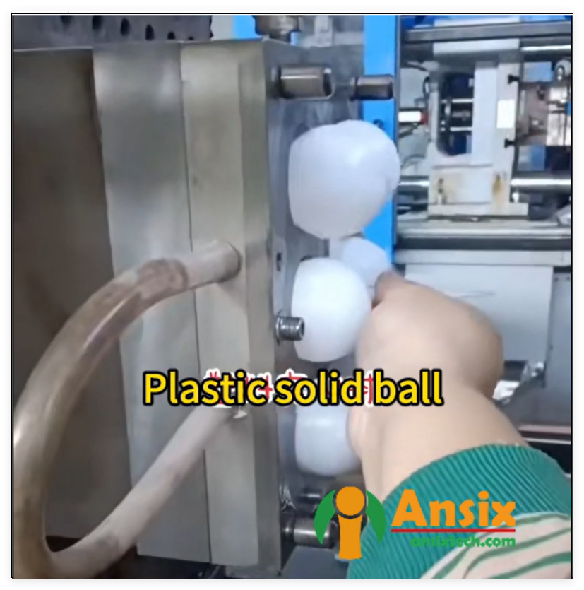


PP solid float foam injection molding
FEATURES
“Hard Power” Backbone (Earning Customer Trust through Equipment Foundation)
Ansix’s manufacturing infrastructure is designed to eliminate the most common customer concerns about precision, consistency, and production reliability.
Mold Manufacturing Equipment
5‑axis high‑speed machining centers capable of machining complex curved surfaces with 0.002 mm accuracy, ensuring that parting lines on float components are smooth and completely free of burrs or visible mismatch.
Slow‑wire EDM capable of machining 0.03 mm fine micro‑holes and narrow slots, allowing the creation of delicate venting features and thin‑wall geometries without warpage or distortion.
Complete in‑house electrode machining center and EDM workshop, meaning mold modifications can be completed without outsourcing – typical repair turnaround is within 24 hours.
-
Mold Description
Product Materials:
PP FOAM
Mold Material:
S136ESR
Number of Cavities:
6
Glue Feeding Method:
Hot runner
Cooling Method:
Water cooling
Molding Cycle
32.5s

- The mold manufacturing process and product material selection
Injection Molding Machine Fleet
Locking force range from 30 tons to 4,000 tons, covering everything from tiny precision floats to large industrial buoyancy components.
All‑servo electric drives delivering ±0.1% repeatable precision – every molding shot is identical to the last, ensuring that PP foam floats maintain consistent buoyancy across millions of parts.
Full machine connectivity to a Manufacturing Execution System (MES) where all process parameters (temperature, pressure, speed, time) are locked and can only be adjusted by authorized engineers, with first‑article and last‑article comparison for every batch.
Inspection & Quality Equipment
Coordinate measuring machines (CMM) and optical image measuring systems are used for full‑dimension inspection.
Every mold set is accompanied by a complete dimensional report before shipment, with critical dimensions held to CPK ≥ 1.33 – a statistical guarantee of process capability that customers can directly verify.
-
What This Means in Customer Value Terms:
A customer does not need to worry about whether the mold fits their injection machine, whether the part dimensions will drift during long production runs, or whether fine feature details will be accurately reproduced. Ansix’s equipment backbone delivers precision that translates into predictable product performance and zero assembly rework.
Core Mold Manufacturing Competitiveness (Quantified Performance that Customers Trust)
Customers care about four things regarding molds: lifetime, precision, delivery time, and repair cost. Ansix addresses each with concrete, verifiable metrics.
Mold Lifetime – The Customer’s “Money Printer”
Mold Component Material Options Lifetime Guarantee (Glass‑Fiber‑Filled PP) Lifetime Guarantee (Unfilled PP)
Mold base P20 / 1.2738 (30–35 HRC) 500,000 cycles 1,000,000 cycles
Core / cavity S136, 1.2344, 1.2343, 8407, SKD11/61, DC53, NAK80, H13, M340, 9Cr18, 4Cr13 (45–50 HRC, hardened & tempered) 500,000 cycles 1,000,000 cycles
Corrosion‑/wear‑resistant S136 ESR, 1.2083, hardened tool steels with nitriding (>60 HRC) Recommended for glass‑filled PP Optional
Every mold is supplied with a material certificate and heat‑treatment curve, providing full traceability.
Achievable Tolerances
Conventional structural parts: ±0.05 mm
Precision gears / medical components: ±0.005 mm
PP foam floats requiring high buoyancy accuracy: ±0.01–0.05 mm
Mold Types Available
Hot runner molds – eliminate runner waste, ideal for high‑volume PP float production
Stack molds – double the output per machine cycle
Two‑color / multi‑material molds – for floats with overmolded magnets or sealing lips
High‑gloss molds – Ra < 0.05 μm surface finish for transparent or visually critical parts
Gate System Optimization – Eliminating Buoyancy Variations
For PP foam floats, gate location and design directly affect foam cell distribution and thus float buoyancy. Ansix uses Moldflow analysis to predict weld‑line positions, gas‑trapping zones, and filling balance before cutting any steel. For a typical PP foam float with wall thickness ranging from 1.6 mm to 3.5 mm, the simulation verifies that the gate is positioned to achieve balanced filling and uniform cell growth, preventing density gradients that would cause the float to list or sink.
Mold Delivery Standards
Simple molds: 10 days
Medium‑complexity: 25–45 days
Expedited service available – even compressed schedules maintain all verification steps (no shortcuts on T0–T3 sampling).
What This Means in Customer Value Terms:
The customer does not buy a mold; they buy production uptime. Ansix’s mold guarantees mean that unexpected mold failures will not interrupt their production schedule. The DFM (Design for Manufacturability) process ensures that by the time the mold is shipped, all potential floatability, warpage, and venting risks have already been eliminated.
Section 3 – Process Control in Injection Molding (Lowering Customer’s Quality Anxiety)
Customers fear: shrinkage, flash, dimensional drift, and batch‑to‑batch color or density variation. Ansix’s process controls are specifically designed to eliminate these fears.
Process Standardization
Every injection molding machine is connected to the MES system, where all parameters (melt temperature, mold temperature, injection pressure, injection speed, holding pressure, cooling time) are locked. Only authorized engineers can adjust settings.
First‑article and last‑article inspection for every production batch ensures that the first part and the 10,000th part are identical within tolerance.
Dimensional Stability Control
Mold temperature zones are independently controlled using manifold water systems.
The temperature difference between core and cavity is maintained within 2 ℃ – critical for preventing warpage in PP foam floats.
A real‑time ultrasonic wall‑thickness sensor is installed on the injection machine, allowing the system to automatically compensate holding pressure if thickness drifts.
Conformal cooling channels (water channels placed 12–20 mm from the cavity, spacing 3–5 mm, flow rate ≥0.5 m/s) provide uniform cooling, with the mold temperature difference held below 3 ℃ for precision parts.
Typical result: For a PP bracket produced over three consecutive weeks, the critical hole‑to‑hole distance variation is ≤0.02 mm.
Surface Quality & Aesthetics
Achievable grades:
Transparent parts: bubble‑free, no flow marks
Plated parts: no gas marks
High‑gloss parts: surface roughness Ra ≤ 0.2 μm
For parts that will be painted or printed, Ansix pre‑engineers warpage compensation into the mold, so printed registration can be held to ±0.1 mm even after foaming.
Special Material Capabilities – Proven in Production
Ansix has extensive production experience with a wide range of engineering thermoplastics, including PC/ABS, PC, PPS+40%GF, PEEK, PTFE/PFA, PA6+GF30, PBT, PEI, PPS, LCP, and LSR (liquid silicone rubber). All materials can be processed with fire‑retardant grades (UL94 V‑0 for electrical housings) and UV‑resistant grades validated to 3,000 hours without color change.
What This Means in Customer Value Terms:
Foamed PP floats are especially sensitive to density variation – even small changes in process conditions can alter buoyancy. Ansix’s closed‑loop MES control ensures that every float has the same effective density and therefore the same floating performance, year after year. The customer’s own quality assurance team can approve the first batch and then trust all subsequent batches without repeated destructive testing.
Section 4 – Full‑Process Service (Reducing Customer’s Management Overhead)
Ansix does not simply deliver parts; it delivers a complete, end‑to‑end solution that reduces the customer’s internal engineering, procurement, and quality resources.
Early Involvement – DFM (Design for Manufacturability) Report
Before the customer commits to tooling, Ansix provides a detailed mold feasibility analysis report covering:
Recommended draft angles (≥0.5° for smooth surfaces, ≥1° for textured, ≥1.5° for rough finishes)
Wall‑thickness optimization (target variation ≤20%)
Proposed gate locations and types
Permitted ejector‑pin mark locations and sizes
Venting depth recommendation – for PP foam, vent depth of 0.02–0.03 mm is used to avoid gas traps, and for bubble‑free LSR components, 0.01–0.02 mm.
This DFM report eliminates “surprises” after the mold is cut – the customer knows exactly what is feasible before spending a dollar on tooling.
Trial Molding & Sampling
T0 to T3 trial shots are provided, each accompanied by an improvement report.
Quick‑change inserts allow alternative designs to be tested without building an entirely new mold.
For PP foam floats, the T0 samples are cut and examined microscopically to confirm uniform cell structure and correct density reduction. Cell diameters are verified against the target (typical target for MuCell: 20–50 μm).
Low‑Volume Pilot Production
Before moving to full mass production, Ansix offers 100–500 shot pilot runs. The pilot run includes:
Real‑time yield statistics
CPK calculation for all critical dimensions
Buoyancy testing for float products
Confirmation of cycle‑time stability
Only after the pilot run meets all customer specifications does Ansix transition to full production.
Maintenance & Spare Parts
A set of common wear parts (ejector pins, core inserts) is shipped with every mold.
Mold maintenance is performed every 200,000 cycles as standard practice.
Lifetime repair is available at cost price – Ansix does not use mold repair as a profit center.
What This Means in Customer Value Terms:
The customer does not need to manage multiple vendors for design, prototyping, pilot production, mass production, and mold maintenance. Ansix becomes a single point of accountability, reducing the customer’s supply‑chain management cost by eliminating coordination overhead, logistics complexity, and quality audit duplication.
Section 5 – Competitive Differentiation (Direct Solutions to Common Industry Complaints)
Instead of simply claiming to be “good,” Ansix provides explicit, verifiable answers to the five most common customer complaints in the injection molding industry.
Customer Complaint Ansix’s Direct Solution
“Molds need constant repair, disrupting my production.” Ansix performs 2,000‑shot aging test before mold delivery and provides a written wear report. The mold comes with a three‑year structural warranty (excluding naturally wearing consumables).
“Lots of flash means expensive manual trimming.” Mold parting lines are machined to 0.005 mm fit accuracy. The injection machine uses self‑locking clamping force compensation, keeping flash below 0.03 mm – no manual trimming required.
“Dimensions drift from batch to batch.” All machines are equipped with ultrasonic wall‑thickness sensors and closed‑loop holding‑pressure compensation. In‑mold temperature and pressure sensors enable real‑time adaptive process control. Typical batch‑to‑batch variation on a critical hole spacing: ≤0.02 mm.
“Mold repair takes weeks.” Ansix operates its own electrode machining center and EDM workshop on‑site. Standard weld repair or insert replacement is completed within 24 hours. The mold never needs to be shipped off‑site for common repairs.
“I worry about the mold maker understanding my float’s buoyancy requirements.” Ansix has specific experience with PP foam floats for water‑level sensors, industrial buoyancy devices, and flotation equipment. The DFM process includes a density‑distribution simulation, ensuring that even after foaming, the float’s center of mass and buoyancy remain as designed.
PP Solid Float Foam Injection Molding: Product Introduction, Manufacturing Process, Delivery Efficiency, Quality Assurance, Competitive Cost Control, and After‑Sales Service
Product Introduction
PP solid float foam injection‑molded products combine a solid, smooth outer skin with a microcellular foam core. The solid skin provides abrasion resistance, chemical stability, and a clean surface finish, while the foam core reduces weight and material consumption. Typical applications include:
Industrial buoyancy floats and float sensors
Automotive lightweight components (up to 20% weight reduction while maintaining strength)
Packaging and transport containers
Flotation devices for water treatment and environmental monitoring
Manufacturing Process
The manufacturing process for PP foam floats follows seven distinct stages:
Material Selection – High‑melt‑strength PP grades (e.g., SABIC PP‑UMS with melt strength >65 cN) are selected for their superior foamability. Chemical foaming agents (typically 0.8–1.6% content) or physical foaming agents (supercritical N₂ or CO₂) are used depending on the density target.
Moldflow Analysis (DFM) – The filling pattern is simulated with a 12–15% viscosity reduction to account for the plasticizing effect of the supercritical fluid. Injection velocity is set 25–50% higher than for solid injection, and gates are made 30–50% larger to prevent shear‑induced defects.
Mold Manufacturing – 5‑axis CNC machining, slow‑wire EDM, and electrical discharge machining are used to produce molds with vent depths of 0.02–0.03 mm specifically for foaming applications. Cooling circuits are designed as conformal channels 12–20 mm from the cavity with spacing 3–5× diameter.
Single‑Phase Solution Creation – For physical foaming (MuCell), supercritical N₂ or CO₂ is injected into the molten PP inside the injection barrel under carefully controlled temperature, pressure, and shear conditions to form a single‑phase solution.
Injection & Foaming – The single‑phase solution is injected into the mold cavity. The sudden pressure drop causes the supercritical fluid to come out of solution, creating millions of cell nuclei. The cells grow until the mold is filled, producing a closed‑cell foam structure.
Cooling & Ejection – The conformal cooling system reduces cycle time by 15–30% compared to conventional cooling designs. Mold temperature is controlled to within 3 ℃.
Post‑Processing & Assembly – Parts are optionally overmolded with magnets or metal inserts, assembled, packaged, and shipped.
Delivery Efficiency
260 injection molding machines ranging from 30 to 2,800 tons
Four production bases in China and Vietnam allowing load balancing and geographic proximity to customers
Standard lead times: 25–45 days for medium‑complexity molds, 10 days for simple molds
Expedited service available – mold trials (T0–T3) completed on compressed schedules without skipping any validation steps
Cycle time reduction – MuCell typically reduces cycle time by eliminating the pack/hold phase, with injection velocity 25–50% faster than solid injection
Quality Assurance
ISO9001, ISO13485, IATF16949 certifications
MES‑locked process parameters – no unauthorized adjustments
CPK ≥ 1.33 on all critical dimensions
First‑article and last‑article inspection for every batch
In‑process ultrasonic wall‑thickness monitoring and closed‑loop compensation
Full material traceability – each batch of PP resin is documented with certificate of analysis
Competitive Cost Control
Material cost reduction – 10–20% (or up to 30%) less resin per part through foaming
Energy cost reduction – lower injection pressures and elimination of the pack/hold phase reduce machine energy consumption
Mold life extension – lower injection pressures mean less wear on mold cavities; typical lifetime 500,000–1,000,000 cycles
Labor cost reduction – flash ≤0.03 mm eliminates post‑mold trimming operations
Logistics cost reduction – multiple production bases shorten shipping distances and reduce transportation costs
After‑Sales Service Commitment
24‑hour mold repair – on‑site EDM and machining center
Spare parts kit – ejector pins, core inserts, and wear components shipped with every mold
Mold maintenance – performed every 200,000 cycles
Lifetime repair at cost – no hidden markups
Technical support – available within 24 hours via email or phone
Customer Value Delivered by Ansix’s Mold Design, Development, and Manufacturing Capabilities
What customer value does Ansix provide?
Ansix provides production reliability rather than just mold hardware. A mold is not a piece of steel – it is a “money printer” that must deliver consistent, high‑quality parts day after day. Ansix designs every mold with the following customer outcomes in mind:
Zero unplanned downtime – the mold will run at least 500,000 shots without structural failure
Zero manual trimming – flash is kept below 0.03 mm
Zero dimensional drift – batch‑to‑batch variation is held to ≤0.02 mm on critical features
Zero budget overruns – the DFM process eliminates “surprises” after tooling is cut
What problems does Ansix solve for customers?
Poor part consistency → Ansix uses MES‑locked parameters, real‑time sensors, and closed‑loop control
Long mold lead times → In‑house EDM and machining center, typical simple mold in 10 days
High scrap rates → CPK≥1.33 guarantees process capability before mass production begins
Difficult assembly → DFM identifies interference and assembly issues before mold construction
Supply chain fragmentation → Single source for design, mold, sampling, production, and after‑sales
How does Ansix perform quality validation?
Moldflow simulation verifies filling balance, weld‑line location, and venting before steel is cut
CMM and optical inspection of every mold component during manufacturing
T0–T3 trial shots with improvement reports at each stage
Pilot run (100–500 shots) with yield and CPK reporting before mass production
Statistical process control during mass production – CPK values reported regularly to the customer
How does Ansix reduce customer costs?
Cost Category Reduction Mechanism Typical Saving
Material cost Foaming reduces PP consumption 10–20% less resin
Energy cost Lower injection pressure + no pack/hold 15–30% energy reduction
Labor cost Flash ≤0.03 mm = no manual trimming Eliminates post‑mold finishing
Mold cost Standardized designs + domestic steel sourcing 20–30% lower than Western toolmakers
Shipping cost Four production bases Lower freight
Quality cost CPK≥1.33 = low defect rate Reduced scrap and rework
How does Ansix increase production capacity and guarantee delivery?
260 injection molding machines spanning 30–2,800 tons, with advanced Japanese (Fanuc, Sumitomo, Toshiba, Nissei, Engel) and German (Arburg) equipment, offering redundant capacity
Four factories in China and Vietnam for load balancing
Hot runner molds reduce cycle time by eliminating runner cooling
Stack molds double output per machine cycle
Real‑time MES monitoring – if a machine drifts out of specification, production is automatically halted until correction
Standard delivery commitment – mold ready for sampling within agreed timeframe; mass production begins within 7–14 days after pilot approval
Complete Manufacturing Solution for PP Solid Float Foam Injection Molding – 2000+ Words Technical Description
1. Project Initiation and Customer Requirement Analysis
When a customer initiates a PP solid float foam injection molding project with Ansix, the process begins with a detailed design review. The customer provides the part geometry, target weight/density, operating environment (e.g., water temperature, chemical exposure), required buoyancy force, expected annual volume, and any regulatory requirements (food contact, UL94 flammability, etc.).
The key challenge with PP solid float foam products is achieving a uniform, closed‑cell foam structure while maintaining a smooth, defect‑free solid skin. The foam structure provides weight reduction and buoyancy, but if the cells are open or non‑uniform, the float will absorb water and lose buoyancy over time. Ansix has developed specific process controls to ensure that PP foam floats remain buoyant indefinitely.
2. Raw Material Selection and Material Characteristics
For PP solid float foam injection molding, material selection is the single most important factor determining product performance. Ansix works with three primary material categories:
Category 1 – High Melt Strength (HMS) PP for Physical Foaming (MuCell)
Example grade: SABIC PP‑UMS (Ultra Melt Strength) with melt strength >65 cN
Characteristics: Excellent foamability, wide processing window (210–280 ℃ melt temperature, 30–50 ℃ mold temperature), low VOC/FOG values, hygienic for food‑contact applications
Application: High‑precision floats requiring density reduction of 20–30% while maintaining excellent surface finish
Category 2 – Impact Copolymer PP for Chemical Foaming
Example grade: PP EPS30R (MFR 1.0–2.0 g/10 min, tensile yield strength ≥24 MPa, flexural modulus 950 MPa)
Characteristics: Balanced mechanical properties, good impact resistance at low temperatures (−20 ℃, notched Izod 4 kJ/m²)
Application: Industrial floats that must survive impacts and temperature cycling
Category 3 – Glass‑Fiber‑Reinforced PP for High‑Strength Floats
Example grade: PP +20% GF (or higher, up to 40% GF)
Characteristics: Increased stiffness, reduced thermal expansion, but more challenging to foam uniformly
Application: Structural floats that must support significant weight or operate in high‑temperature environments
3. DFM (Design for Manufacturability) and Moldflow Analysis
Before any steel is cut, Ansix performs a comprehensive Moldflow simulation specifically adapted for the MuCell foaming process. The simulation deviates from conventional injection molding simulation in several key ways:
Viscosity reduction: A material with 12–15% lower viscosity than the actual PP grade is selected in the simulation to account for the plasticizing effect of the supercritical fluid
Injection velocity: Set 25–50% higher than for solid injection
Gate sizing: Gates are increased by 30–50% to prevent shear‑induced surface defects
Hold pressure: Set to approximately 25% of injection pressure
Pack/hold time: Reduced to 0.5–1 second in actual production (simulated at 2 seconds for software stability)
The simulation evaluates:
Balanced fill pattern – 2 to 4 areas remain unfilled until the end, indicating balanced flow
Weld‑line locations – identified and vented appropriately
Gas traps – race‑tracking that could trap gas is eliminated
Thin sections at end of fill – these limit weight reduction and are redesigned if necessary
Maximum fill pressure – kept below 8,000 psi (approximately 55 MPa) to ensure the part can be produced on standard injection machines
For a typical PP foam float with wall thickness varying between 1.6 mm and 3.5 mm, the simulation verifies that the gate is positioned at the thickest wall section, allowing the foam cells to expand fully before the melt front reaches the end of the cavity. This prevents density gradients that would cause the float to list or sink.
4. Mold Design for PP Solid Float Foam Production
The mold design for PP foam floats differs from conventional injection molds in several critical aspects:
4.1 Mold Steel Selection
Mold Component Recommended Steel Hardness Justification
Mold base P20 or 1.2738 30–35 HRC Good machinability, adequate for high cycle counts
Cavity / core (unfilled PP) S136, NAK80, or 1.2083 45–50 HRC Corrosion resistance, mirror finish capability
Cavity / core (glass‑filled PP) 1.2344 (H13), 1.2343, 8407, or DC53 48–52 HRC Wear resistance for abrasive glass fibers
Slides and lifters SKD11 or 1.2767 55–60 HRC High wear resistance for moving components
The mold is heat‑treated with a documented temperature curve, ensuring uniform hardness throughout. Nitriding may be applied to corrosion‑resistant molds to achieve hardness >60 HRC on the surface while maintaining a tough core.
4.2 Gating System
For PP foam floats, the gate must be large enough to prevent shear‑induced blistering (a common defect in MuCell molding where the high‑velocity melt creates surface blemishes). Typical gate design parameters:
Gate diameter increased 30–50% compared to solid injection
Fan gates or edge gates are preferred over pin gates for float applications
Sub‑gates are avoided if possible – they increase injection velocity and can cause surface splay
4.3 Cooling System Design
Uniform cooling is essential for PP foam floats. Non‑uniform cooling creates differential shrinkage, which leads to warpage and density variation across the float. Ansix uses conformal cooling channels machined into the mold inserts, rather than straight drilled holes:
Channels placed 12–20 mm from the cavity surface
Spacing between channels 3–5 × channel diameter
Coolant flow rate ≥0.5 m/s
Mold temperature controlled to within 3 ℃ across the entire cavity
Cooling water temperature for PP: 15–22 ℃
For complex float geometries with changing cross‑sections, conformal cooling channels follow the part contour, providing uniform heat extraction even around curved surfaces.
4.4 Venting
Proper venting is critical for foam injection molding because trapped gas prevents the foam from expanding fully and creates surface defects. Vent design:
Vent depth at parting line: 0.02–0.03 mm for PP
Vent width: 5–10 mm
Vent length before the land: 1–2 mm
Additional venting at weld‑line locations identified by Moldflow simulation
4.5 Ejection System
Ejector pins must be positioned to avoid marking critical surfaces of the float. For foam floats, the ejector pin marks are located on non‑functional surfaces (e.g., the bottom of the float where buoyancy is measured, or the inside diameter of a mounting hole). The ejection stroke extends ≥5 mm beyond the part height to ensure clean release.
5. Mold Manufacturing Process and Challenges
5.1 Mold Manufacturing Workflow
CAD design – using UG/NX or AutoCAD with full assembly modeling
CAM programming – 5‑axis toolpaths for complex curved surfaces
Rough machining – removing 80% of material on CNC milling centers
Heat treatment – quenching, tempering, and nitriding as specified
Semi‑finish machining – creating the base cavity shape
EDM (sinker and wire) – for sharp internal corners, narrow slots (0.03 mm capability), and detailed features
Graphite electrode machining – for complex cavity details where EDM is required
Hand finishing and polishing – achieving the specified surface finish (Ra ≤ 0.2 μm for high‑gloss parts)
Assembly – fitting slides, lifters, ejector pins, and cooling fittings
Inspection – CMM and optical measurement, full dimensional report
5.2 Key Manufacturing Challenges for PP Foam Float Molds
Challenge 1 – Maintaining uniform vent depth
Vent depth directly affects foam cell formation. If the vent is too deep (≥0.04 mm for PP), the melt will flash out. If it is too shallow (<0.015 mm), gas cannot escape and surface defects appear. Ansix uses precision EDM and hand finishing to achieve the exact 0.02–0.03 mm vent depth across the entire parting line.
Challenge 2 – Machining conformal cooling channels
Conformal cooling channels are curved and follow the part contour, requiring 5‑axis CNC machining or additive manufacturing techniques. Ansix’s 5‑axis high‑speed machining centers can produce these channels with 0.002 mm accuracy.
Challenge 3 – Achieving high polish on cavity surfaces
PP foam floats often require a smooth surface to prevent marine growth or for aesthetic reasons. Polishing to Ra < 0.05 μm requires diamond compounds and skilled hand finishing. Ansix’s polishing workshop is equipped to achieve high‑gloss finishes on S136 and NAK80 steels.
Challenge 4 – Managing thermal expansion in multi‑cavity molds
For high‑volume float production, multi‑cavity molds (4, 8, or 16 cavities) are used. Each cavity must be temperature‑controlled independently to ensure identical foam cell structure across all cavities. Ansix uses independent water manifolds and individual thermocouples for each cavity, with mold temperature controlled to ±1 ℃ across the entire mold face.
6. Injection Molding Process for PP Solid Float Foam
6.1 MuCell Physical Foaming Process
The MuCell process for PP foam floats follows these steps:
Step 1 – Single‑phase solution creation: Supercritical N₂ (or CO₂) is injected into the molten PP inside the injection barrel. The supercritical fluid is completely dissolved into the polymer under carefully controlled pressure, temperature, and shear conditions. The restriction‑element mixing screw creates the single‑phase solution where the gas is uniformly dispersed at the molecular level.
Step 2 – Pressurized storage: The single‑phase solution is maintained in a pressurized state inside the barrel until the start of injection. A shutoff nozzle prevents premature expansion.
Step 3 – Injection: The shutoff nozzle opens, and the single‑phase solution is injected into the mold cavity at high velocity (25–50% faster than solid injection). As the solution passes through the gate, the sudden pressure drop causes the supercritical fluid to come out of solution, creating millions of cell nuclei simultaneously.
Step 4 – Cell growth and cavity filling: The cell nuclei grow until the mold cavity is filled. Because the cells expand to fill the cavity, there is no separate pack/hold phase. The cells continue to expand until the melt front freezes at the mold wall.
Step 5 – Cooling: The conformal cooling channels extract heat uniformly, solidifying the part. The part ejects with a solid skin (formed where the melt touched the cooled mold wall) and a microcellular foam core.
6.2 Process Parameter Optimization
Parameter Recommended Range for PP Foam Float Effect on Product
Melt temperature 210–280 ℃ Higher temperature increases expansion ratio but may cause cell coalescence
Mold temperature 30–50 ℃ (physical foaming); 50–80 ℃ (chemical foaming) Lower mold temperature creates thicker solid skin but may slow filling
Injection speed 25–50% faster than solid injection Faster speed prevents premature cell growth before cavity is filled
SCF dosage (N₂) 0.3–1.0% by weight Higher dosage = greater weight reduction, but more risk of surface defects
Back pressure Increased above solid injection level Maintains single‑phase solution stability during plastication
Cooling time Reduced 15–30% vs. solid injection Foamed parts cool faster because there is less polymer mass
6.3 Injection Molding Challenges Specific to PP Foam Floats
Challenge 1 – Density variation across the float
If the mold filling is imbalanced, cells grow more in some regions than others, creating density variation that causes the float to list. Solution: Moldflow simulation with balanced gate design and conformal cooling ensures uniform density distribution.
Challenge 2 – Surface splay or blistering around the gate
The high injection velocity can create shear‑induced defects at the gate. Solution: Increase gate size by 30–50% and profile injection velocity (slower near the gate, faster after the gate is filled).
Challenge 3 – Open cells on the surface
If the melt front advances too slowly or the mold temperature is too high, cells can reach the surface and create an open‑cell structure that absorbs water. Solution: Maintain mold temperature on the lower end (30 ℃) and ensure adequate shot volume to keep the melt front advancing quickly.
Challenge 4 – Inconsistent weight reduction batch to batch
Small changes in SCF dosage, melt temperature, or back pressure change the foam density. Solution: MES‑locked parameters and real‑time SCF flow monitoring ensure each shot uses exactly the same amount of supercritical fluid.
7. Quality Control and Assurance
Ansix applies a multi‑layer quality control system for PP foam float production:
Incoming material QC: Each batch of PP resin is tested for MFR, moisture content, and filler percentage. Certificates of analysis are retained for traceability.
In‑process QC:
Ultrasonic wall‑thickness sensor on the injection machine provides real‑time thickness data. If thickness drifts beyond specified limits (typically ±0.05 mm), the machine automatically compensates holding pressure or stops.
In‑mold temperature and pressure sensors monitor cavity conditions. The data is logged to the MES system.
Every 100th shot is captured for dimensional measurement on an optical comparator or CMM.
Statistical process control (SPC): Critical dimensions are tracked with CPK values. Ansix guarantees CPK ≥ 1.33 for dimensions specified by the customer. Typical CPK values for PP foam floats on key buoyancy‑affecting dimensions exceed 1.67.
Density verification: For float products, density is directly measured by weighing the part in air and in water (Archimedes method). Parts falling outside the specified density range (e.g., ±2% of target) are rejected and the process is adjusted.
Visual inspection: Parts are inspected for surface defects: splay, blisters, voids, flash, and flow marks. Acceptance criteria are defined jointly with the customer (e.g., no visible splay on the top surface of the float).
Final QC before shipment: Each batch is accompanied by a certificate of conformance, material traceability report, dimensional report (for sampled parts), and density verification records.
8. Efficiency Improvement and Cost Reduction Strategies
8.1 Efficiency Improvement from MuCell Technology
Efficiency Metric Solid PP Injection MuCell PP Foam Improvement
Material usage per part 100% (solid) 80–90% (foamed) 10–20% less material
Cycle time Baseline 15–30% shorter Faster production
Injection pressure Baseline Up to 50% lower Reduced machine wear
Clamp tonnage requirement Baseline Up to 30% lower Smaller press possible
Pack/hold phase Yes (3–8 seconds) Eliminated Direct cycle time reduction
8.2 Cost Reduction Strategies
Material cost reduction – Foaming reduces PP consumption by 10–20% without changing the functional dimensions of the part. For a customer producing 1 million floats per year, this alone can save 10–20 tons of PP annually.
Energy cost reduction – MuCell operates at lower injection pressures and without a pack/hold phase, reducing machine energy consumption by an estimated 15–30%.
Mold life extension – Lower injection pressures reduce mechanical stress on the mold, extending its useful life by 20–40% compared to solid injection of the same geometry.
Labor cost reduction – Flash is held to ≤0.03 mm, eliminating manual trimming operations. Parts eject cleanly, reducing the need for operator intervention.
Logistics cost reduction – Lighter parts reduce shipping weight. For air‑freighted or fuel‑sensitive logistics, this is a direct cost saving.
Quality cost reduction – CPK≥1.33 and MES‑locked parameters produce consistent parts, reducing scrap rates from typical industry 3–5% down to <1% for qualified processes.
9. Quality Validation – Pilot Production and Mass Production Transfer
Before any PP foam float project moves from development to mass production, Ansix executes a structured quality validation plan:
Step 1 – T0 trial (first shot from the mold)
Verify that the mold fills completely without short shots
Check that ejection operates correctly
Measure part dimensions and compare to CAD
Cut and examine foam cell structure microscopically
Step 2 – T1 trial (after initial adjustments)
Adjust gates, vents, and cooling based on T0 findings
Run 50–100 shots
Measure CPK on all critical dimensions
Adjust process parameters to achieve target weight reduction
Step 3 – T2 trial (optimization trial)
Run 200–500 shots
Perform density uniformity test – cut floats into sections and measure density at multiple points
Conduct buoyancy verification (if specified)
Document optimal process parameters
Step 4 – Pilot production (100–500 shots)
Run on the actual production injection machine (not the development machine)
Use the same operators who will run mass production
Collect yield and CPK data
Obtain customer sign‑off before proceeding to mass production
Step 5 – Initial mass production run
First 1,000 shots produced with 100% dimensional inspection
First‑article inspection report provided to customer
After 1,000 confirmed good parts, transition to periodic sampling (e.g., every 500 parts)
Step 6 – Ongoing SPC
Critical dimensions charted on Xbar‑R charts
CPK recalculated weekly for high‑volume programs
Out‑of‑control conditions trigger immediate process investigation and correction
10. Packaging and Rapid Delivery
Packaging standards
PP foam floats are packaged in quantities and configurations agreed with the customer. Typical options include:
Bulk bags (500–2,000 parts per bag) – for high‑volume, non‑cosmetic applications
Layer trays with separators – for parts requiring surface protection
Custom dunnage – for float assemblies that include magnets or overmolded metal components
Each package is labeled with part number, quantity, batch number, date of manufacture, and certification status.
Delivery logistics
Standard delivery: 15–30 days from order confirmation for mass production quantities
Expedited delivery: Available for emergency orders (additional freight charges apply)
Kanban / Just‑in‑time (JIT) programs: Ansix can hold safety stock and deliver on a pull‑signal basis for customers with predictable demand
11. Industry Experience and Proven Reliability
With over 28 years of manufacturing experience and 260 injection molding machines in operation, Ansix has executed projects across multiple demanding industries:
PP foam floats for water‑level sensors – achieving ±2% density uniformity and water absorption <1% after 1,000 hours of immersion
Automotive lightweight components – including parts for Mercedes‑Benz, achieving 15–20% weight reduction while meeting all mechanical performance requirements
Medical device housings – processed in ISO13485‑certified facilities and ISO Class 8 cleanrooms
Electrical enclosures (UL94 V‑0 rated) – using flame‑retardant PP compounds
Industrial flotation and buoyancy products – operating continuously in water, chemical, and wastewater environments
12. Cost Reduction – Quantified Examples
Example 1 – High‑volume PP float (2 million pieces per year)
Cost Factor Solid PP Production MuCell Foamed PP Production Annual Saving
Material cost (PP at $1.50/kg) $90,000 $72,000 (20% less resin) $18,000
Energy cost $15,000 $10,500 (30% reduction) $4,500
Post‑mold labor (trimming) $8,000 $0 (flash ≤0.03 mm) $8,000
Scrap cost (3% vs 1%) $2,700 $720 $1,980
Total annual saving $32,480
Example 2 – Large industrial float (50,000 pieces per year)
Cost Factor Solid PP Production MuCell Foamed PP Production Annual Saving
Material cost (PP at $1.50/kg) $112,500 $90,000 $22,500
Mold maintenance (200,000 cycles) 2 maintenance events/year 1.5 events/year 25% reduction
Shipping weight (reduced by 18%) $25,000 $20,500 $4,500
Total annual saving $27,000 + mold maintenance saving
Closing Statement to Customer
“Dear Customer, for us, a mold is not a piece of steel – it is a money printer. When we design your mold for PP solid float foam injection, we simultaneously plan the flow geometry, the venting paths, the temperature balance, and the wear resistance so that when the mold arrives on your production floor, it runs with zero debugging, minimal flash, and exceptionally long life. We invite you to select one of your existing products – or a proposed new one – and let us walk you through a complete DFM report. You will see directly how we predict and eliminate the risks of weld lines, gas traps, shrinkage marks, and density non‑uniformity before we ever cut a single piece of steel.”
Ansix Tech – your single‑source partner for PP solid float foam injection molding, from design and mold manufacturing through pilot production, mass production, quality validation, and after‑sales support.
Ansix Tech Co Ltd
If you have any plans related to PP solid float foam injection molding , you can contact us at any time. We will turn your ideas into reality, let you realize your dreams, and obtain large orders from the market. Our contact information is info@ansixtech.com. Or contact our CTO, mail: stephen@ansixtech.com
#www.ansixtech.com #ansixtech.com #PP solid float foam injection molding #PP solid float foam injection molding injection molding companies #PP solid float foam injection molding Canopy Mold injection mold companies #Ansix #Ansix moulds #Ansix china #Ansix tech china #Ansix tech company #Ansix facotry #PP solid float foam injection molding injection molding #PP solid float foam injection molding injection tools #PP solid float foam injection molding injection moulds #PP solid float foam injection molding plastic mould #PP solid float foam injection molding plastic tools #Ansix Tech #Ansix molds #Ansix injection molding #Ansix mold factory #injection molding PP solid float foam injection molding#Ansix mold factory #PP solid float foam injection molding china #PP solid float foam injection molding molds #injection factory #PP solid float foam injection molding injection molding #PP solid float foam injection molding injection molding factory #injection molding company #PP solid float foam injection molding injection mold companies #PP solid float foam injection molding Tooling #PP solid float foam injection molding mold limited #Ansix mold china #Ansix companies #Ansix company China #PP solid float foam injection molding facotry #Ansix Tech #Ansix Tech mould #PP solid float foam injection molding injection moulding #injection moulding company #Ansix PP solid float foam injection molding parts injection mold companies #medical injection molding companieschina #PP solid float foam injection molding china factory #Ansix moulding companies #Ansix molding company #PP solid float foam injection molding injection moulding facotry #Ansix Tech mold #PP solid float foam injection molding mould #PP solid float foam injection molding plastic injection molding #ansix plastic mold #Mold manufacturing #PP solid float foam injection molding parts manufacturing #PP solid float foam injection molding plastic parts factory #PP solid float foam injection molding injection parts mold #PP solid float foam injection molding PRECISION MANUFACTURING #PP solid float foam injection molding #China mold #PP solid float foam injection molding injection moulding china #PP solid float foam injection molding mould china #china precision mold #mold in china #PP solid float foam injection molding mold china #Precision molds #High-precision molds #PP solid float foam injection molding #Injection molds #PP solid float foam injection molding Factory #PP solid float foam injection molding Company #Super Large Injection Mold Factory #Large Tonnage Injection Molding Factory #PP solid float foam injection molding Company #PP solid float foam injection molding Factory #2800T Injection Molding Factory #3000 Ton Injection Molding #4500 Ton Injection Molding Factory #Large Mold Injection Molding #Large Plastic Mold Injection Molding Factory #Large Injection Mold Manufacturer #Plastic Mold Factory #Injection Mold #Plastic Mold